Controller for DC/DC converter
A technology of DC converters and control devices, applied in the direction of output power conversion devices, control/regulation systems, instruments, etc., which can solve problems such as errors, different offsets, and large transformers, so as to suppress costs and simplify configurations Effect
- Summary
- Abstract
- Description
- Claims
- Application Information
AI Technical Summary
Problems solved by technology
Method used
Image
Examples
Embodiment 1
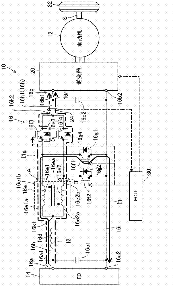
[0040] figure 1 It is a schematic diagram generally showing the control device of the DC / DC converter according to the first embodiment of the present invention.
[0041] exist figure 1 In , symbol 10 represents a vehicle. The vehicle 10 is composed of a fuel cell vehicle, and is equipped with a rotating electrical machine 12 (indicated by "electric motor" in the figure), a fuel cell (indicated by "FC" in the figure) 14, DC / DC converter 16 and inverter 20.
[0042] The rotating electric machine 12 is constituted by a brushless AC synchronous motor, and transmits a rotational output to wheels (drive wheels) 22 via a connecting shaft S when energized, thereby driving the vehicle 10 . The rotary electric machine 12 has a regenerative function of converting kinetic energy generated with the rotation of the connecting shaft S into electric energy and outputting the electric energy during deceleration. That is, the rotary electric machine 12 functions as a motor (motor) when energ...
Embodiment 2
[0096] Next, a control device for a DC / DC converter according to a second embodiment of the present invention will be described.
[0097] The description will focus on the points of difference from the first embodiment. In the second embodiment, the DC / DC converter 16 is mounted on a hybrid electric vehicle (HEV).
[0098] Figure 7 is a whole representation of the control device of the DC / DC converter according to the second embodiment and figure 1 Same sketch.
[0099] Such as Figure 7 As shown, a hybrid vehicle 100 includes an internal combustion engine (hereinafter referred to as "engine") 102 as a drive source in addition to a rotary electric machine 12 . The engine 102 is a gasoline-injected spark ignition type and has four cylinders, and is connected to a rotary electric machine 12 via a drive shaft S1 , and outputs of the rotary electric machine 12 and the engine 102 are input to a transmission 104 . The transmission 104 changes the speed of these outputs and tran...
Embodiment 3
[0104] Next, a control device for a DC / DC converter according to a third embodiment of the present invention will be described.
[0105] The description will focus on the points of difference from the first embodiment. In the third embodiment, the DC / DC converter 16 is mounted on an electric vehicle (EV).
[0106] Figure 8 is the overall representation of the control device of the DC / DC converter according to the third embodiment and figure 1 Same sketch.
[0107] Such as Figure 8 As shown, an electric vehicle 200 is equipped with a battery 202 instead of the fuel cell 14 of the first embodiment. The battery 202 is constituted by a secondary battery (storage battery) such as a lithium ion battery, as in the second embodiment.
[0108] Thus, in the third embodiment, since the DC / DC converter 16 is configured to be mounted on the electric vehicle 200, in the electric vehicle 200, the size of the transformer 16e can be increased without increasing the size of the transforme...
PUM
 Abstract
Description
Claims
Application Information
 - R&D
- Intellectual Property
- Life Sciences
- Materials
- Tech Scout
- Unparalleled Data Quality
- Higher Quality Content
- 60% Fewer Hallucinations
Browse by: Latest US Patents, China's latest patents, Technical Efficacy Thesaurus, Application Domain, Technology Topic, Popular Technical Reports.
© 2025 PatSnap. All rights reserved.Legal|Privacy policy|Modern Slavery Act Transparency Statement|Sitemap|About US| Contact US: help@patsnap.com


