
Tail gas heat exchanger of diesel engine

A diesel engine and heat exchanger technology, applied in the direction of heat exchanger shell, indirect heat exchanger, heat exchanger type, etc., can solve the problems of exhaust heat energy not being utilized, deterioration of surrounding working environment, waste of heat energy, etc., and achieve production cost Low, improve the working environment, the effect of high heat exchange efficiency

Inactive Publication Date: 2013-01-23
泰州市远望换热设备有限公司
View PDF5 Cites 3 Cited by
  • Summary
  • Abstract
  • Description
  • Claims
  • Application Information

AI Technical Summary

Problems solved by technology

The supporting diesel engine in the project usually directly discharges the exhaust gas. Even if a purification device is installed, it can only purify carbon particles and reduce the pollution of visible objects, but the heat energy in the exhaust gas is not utilized.
If the exhaust gas emitted by the diesel engine is not comprehensively treated, it will not only waste heat energy, but also deteriorate the surrounding working environment

Method used


Image

  • Tail gas heat exchanger of diesel engine
  • Tail gas heat exchanger of diesel engine
  • Tail gas heat exchanger of diesel engine

Examples


Embodiment Construction

[0014] The present invention will be further described below according to the accompanying drawings and in conjunction with the embodiments.

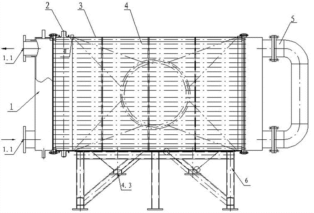
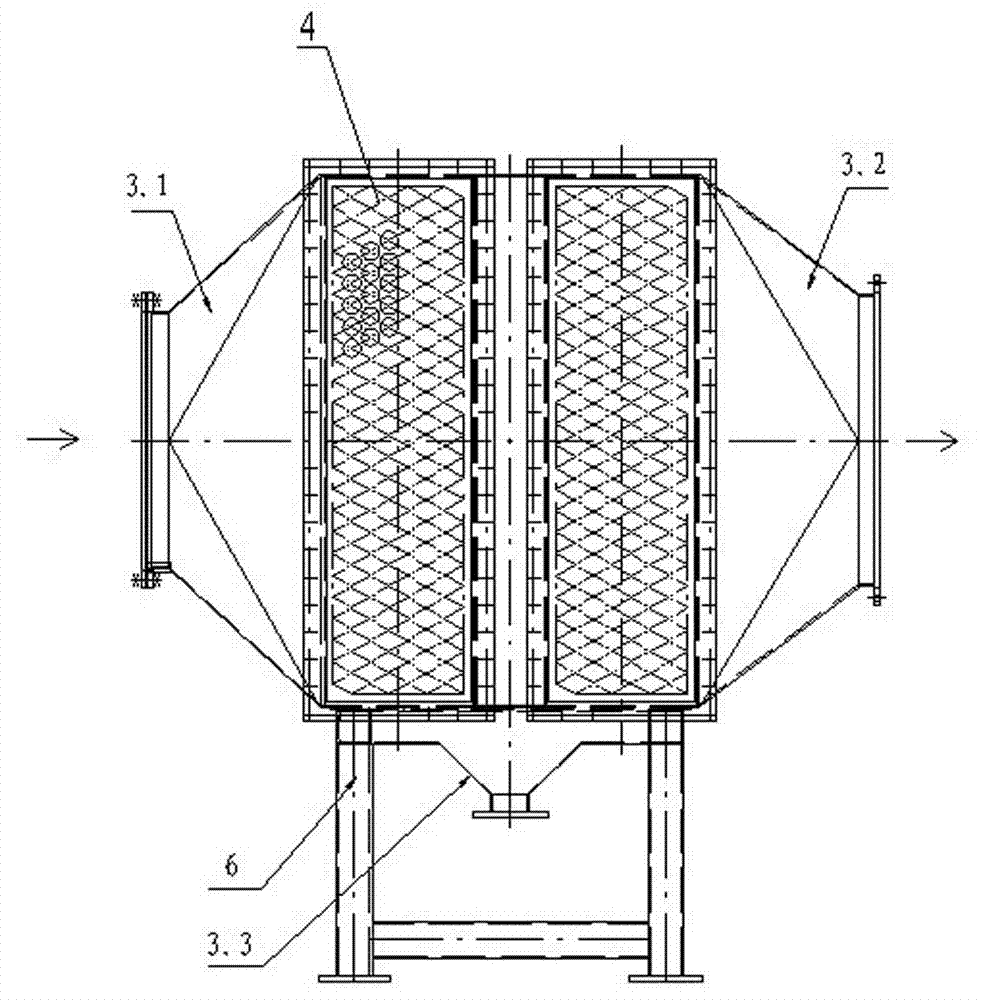
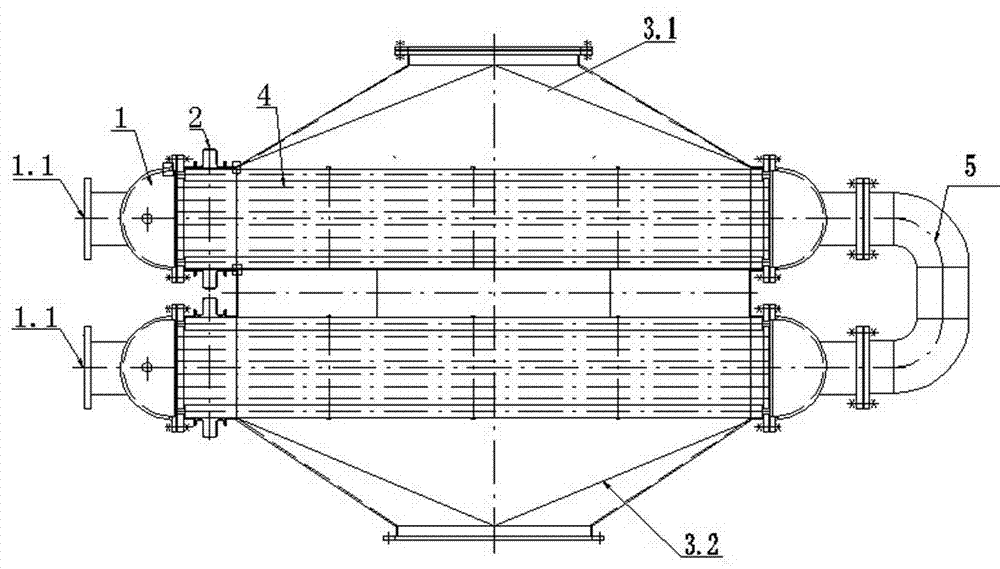
[0015] figure 1 The shown diesel engine exhaust heat exchange device includes a water collection chamber 1 , an expansion joint 2 , an insulation shell 3 , a heat exchange tube assembly 4 , an elbow 5 and a bracket 6 . The water collection chamber 1 is a semicircular groove-shaped cavity, and one end of the outer wall is provided with a connecting pipe 1.1 as a channel for introducing or discharging water flow. The heat exchange tube assembly 4 is a rectangular body in a lying position, the left end surface is sealed and connected to the water collection chamber 1 through the expansion joint 2, and the right end surface is directly sealed and connected to the water collection chamber 1 to form a heat exchanger unit. The heat-insulating shell 3 is a rectangular thin-plate member provided with a heat-insulating layer, and the heat-insula...


PUM


Abstract

The invention discloses a tail gas heat exchanger of a diesel engine. The tail gas heat exchanger comprises water collection chambers, expansion joints, a thermal insulation shell, heat exchange tube components, elbows and a support. The left end faces of the heat exchange tube components are in sealed connection with the water collection chambers through the expansion joints, and the right end faces of the heat exchange tube components are in sealed connection with the water collection chambers directly so as to form heat exchanger units. The thermal insulation shell is arranged on the support, and the thermal insulation shell of a three-way structure is transversely provided with two heat exchanger units with the same specification in an inner chamber between a tail gas inlet and a tail gas outlet in parallel. The water collection chambers connected to both ends of the heat exchanger units are exposed out of the thermal insulation shell, connecting pipes of the two adjacent water collection chambers at the left end are respectively taken as introduction or drainage water flow passages, and connecting pipes of two adjacent water collection chambers at the right end are connected to form an integrated structure through an elbow string. According to the invention, through heat exchange of circulating cooling water and waste gas, the waste heat is utilized, and the national energy conservation and emission reduction policy is realized. The invention is particularly matched with a high-power diesel engine fixed by a working position.

Description

technical field [0001] The invention relates to a gas-liquid heat exchange device, in particular to a heat exchange device using exhaust gas from a diesel engine as a heat source. Background technique [0002] When the diesel engine is working, the temperature of the exhaust gas continuously discharged from the exhaust port is as high as 300 ° C ~ 450 ° C. In addition to harmful substances such as nitrogen oxides and carbon particles that pollute the environment, the exhaust gas is also accompanied by a large amount of heat energy emission, especially for high-power diesel engines. The exhaust emission is large, and the heat energy loss is greater. The supporting diesel engines in the project usually emit exhaust gas directly. Even if a purification device is added, it can only purify carbon particles and reduce the pollution of visible objects, while the heat energy in the exhaust gas is not utilized. If the exhaust gas emitted by the diesel engine is not comprehensively t...

Claims


Application Information

Patent Timeline
Patent Type & Authority Applications(China)
IPC IPC(8): F01N5/02F01N3/04F28D7/00F28F9/26
CPCY02T10/16Y02T10/12
Inventor 吴旭东左小东戴燕曹润陆俊霞
Owner 泰州市远望换热设备有限公司
Learn More