Composite frequency-selective-surface invisible radome
A frequency-selective surface and radome technology, applied in the microwave field, can solve the problems of non-deployment, large incident angle of electromagnetic waves, and difficult process implementation, so as to reduce the difficulty of implementation, reduce backscattering, and reduce RCS.
- Summary
- Abstract
- Description
- Claims
- Application Information
AI Technical Summary
Problems solved by technology
Method used
Image
Examples
specific Embodiment approach 1
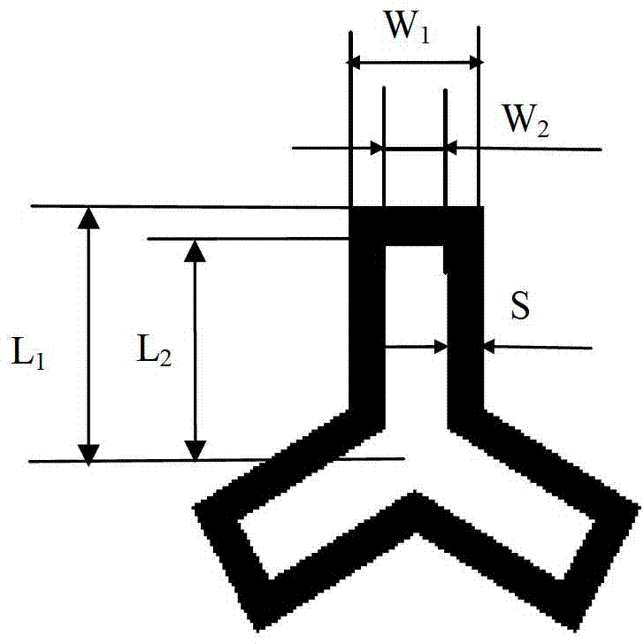
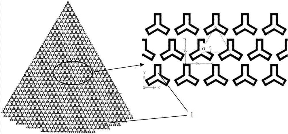
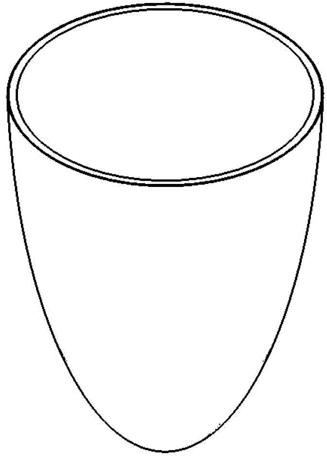
[0028] Specific implementation mode 1. Combination Figure 1 to Figure 8 Describe this embodiment, a kind of composite frequency selective surface stealth radome, this composite frequency selective surface stealth radome is laminated by the frequency selective surface flexible film on the outer surface of the conical inner cover to form the frequency selective surface inner cover, and then use The special lamination equipment embeds and laminates the frequency selective surface inner cover into the outer radome to form a composite frequency selective surface stealth radome. The frequency selective surface flexible film is composed of a Y ring unit 1, and the Y The ring units 1 are periodically arranged in an equilateral triangle, and the parameters of the periodic arrangement are respectively, the arrangement period Dx of the Y ring unit 1 in the x direction is 7 mm, and the arrangement period Dy in the y direction is 6.062 mm. The period angle α is 60o.
[0029] The structur...
specific Embodiment approach 2
[0032] Specific embodiment two, combine Figure 2 to Figure 8 Describe this embodiment. This embodiment is a method for manufacturing a compound frequency selective surface stealth radome described in Embodiment 1. The specific preparation process is divided into three stages: conical inner cover design, simulation calculation and process preparation. :
[0033] 1. The design stage of the conical inner cover: the design space of the conical inner cover is calculated according to the size of the outer radome, the radar antenna 3 and the scanning angle of the working state of the radar antenna 3. It must be ensured that the FSS conical inner cover is embedded in the antenna and the outer surface. Between the radomes, the normal scanning of the radar antenna 3 is not affected. Then calculate the incidence angle converted into the FSS when the electromagnetic wave is incident on the conical inner cover with different cone angles, and the change range of the incident angle of the ...
PUM
| Property | Measurement | Unit |
|---|---|---|
| thickness | aaaaa | aaaaa |
| relative permittivity | aaaaa | aaaaa |
Abstract
Description
Claims
Application Information
 - R&D
- Intellectual Property
- Life Sciences
- Materials
- Tech Scout
- Unparalleled Data Quality
- Higher Quality Content
- 60% Fewer Hallucinations
Browse by: Latest US Patents, China's latest patents, Technical Efficacy Thesaurus, Application Domain, Technology Topic, Popular Technical Reports.
© 2025 PatSnap. All rights reserved.Legal|Privacy policy|Modern Slavery Act Transparency Statement|Sitemap|About US| Contact US: help@patsnap.com


