Fixture pressing mechanism for flexible circuit board

A technology of flexible circuit board and pressing mechanism, which is applied in the direction of the measuring device shell, etc., can solve the problems of difficult to achieve the test purpose, the inability to connect the terminal electrically, and the probe breakage of the needle connector, so as to improve the alignment accuracy and Test efficiency, protection from being crushed, and effects of avoiding probe breakage

Inactive Publication Date: 2013-01-16
AU OPTRONICS (SUZHOU) CORP LTD +1
View PDF0 Cites 14 Cited by
  • Summary
  • Abstract
  • Description
  • Claims
  • Application Information

AI Technical Summary

Problems solved by technology

[0003] The needle connector includes a test platform, a pressure plate and an indenter. When the pressure plate is pressed down at a certain angle, since the indenter has an inclined initial angle with the top surface of the flexible circuit board of the liquid crystal panel, the indenter is opposite to the flexible circuit board. When the applied force is uneven, it is easy to cause the flexible circuit board to shift during the pressing process of the indenter and the flexible circuit board, resulting in the flexible circuit board being warped or damaged
In addition, it is difficult to ensure the alignment accuracy between the indenter and the flexible circuit board, which often causes the probe of the pin connector of the test circuit board to break or cannot be electrically connected to the corresponding terminal of the flexible circuit board, so it is difficult to achieve the expected Testing purposes
[0004] In view of this, how to design a fixture pressing mechanism for the above-mentioned test fixture so that the flexible circuit board will not be displaced during the pressing process, and the pin connector and the flexible circuit board It can be reliably aligned to avoid probe breakage caused by inaccurate alignment or the probe cannot be electrically connected to the corresponding terminal of the flexible circuit board, improve alignment accuracy and test efficiency, and protect the flexible circuit board from being crushed. It is an urgent problem to be solved by relevant technical personnel in the industry

Method used


Image

  • Fixture pressing mechanism for flexible circuit board
  • Fixture pressing mechanism for flexible circuit board
  • Fixture pressing mechanism for flexible circuit board

Examples


Embodiment Construction

[0023] In order to make the technical content disclosed in this application more detailed and complete, reference may be made to the drawings and the following various specific embodiments of the present invention, and the same symbols in the drawings represent the same or similar components. However, those skilled in the art should understand that the examples provided below are not intended to limit the scope of the present invention. In addition, the drawings are only for schematic illustration and are not drawn according to their original scale.

[0024] The specific implementation manners of various aspects of the present invention will be further described in detail below with reference to the accompanying drawings.

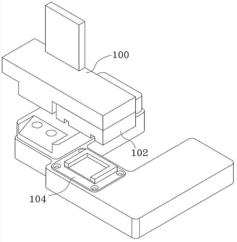
[0025] figure 1 A schematic structural view showing a jig pressing mechanism for a flexible circuit board in the prior art. refer to figure 1 , the connector of the test circuit board (eg, a pin connector with probes) includes a pressure plate 100 , a pr...


PUM


Abstract

The invention provides a fixture pressing mechanism for a flexible circuit board. The fixture pressing mechanism comprises a pressing body, and a base, wherein a location groove and a guide groove are formed on the pressing part on the lower surface of the pressing body; the location groove is formed at the middle part of the guide groove; the base includes a horizontal part and a floating groove raised above the horizontal part; the floating groove can move by a predetermined distance in each dimension; the pressing body is tightly clamped on the base through the fit between the guide groove and the floating groove; and a detection probe in the location groove is electrically connected with a corresponding test pin on the flexible circuit board. In comparison to the prior art, the fixture pressing mechanism provided by the invention can prevent displacement of the flexible circuit board in the pressing process, and the pressing body can be reliably aligned to the flexible circuit board to obviate probe breakage caused by inaccurate alignment, thereby improving the alignment accuracy and the testing efficiency, and protecting the flexible circuit board from being crushed.

Description

technical field [0001] The invention relates to a test fixture, in particular to a fixture pressing mechanism of the test fixture. Background technique [0002] At present, after the liquid crystal panel is assembled, various tests before leaving the factory are generally carried out. During these tests, it is usually necessary to connect the connector of the panel to be displayed, such as a flexible printed circuit (FPC), to the connector of the test circuit board. In the prior art, most of the connectors of the test circuit board adopt pin connectors. When testing the circuit board of the liquid crystal panel, the flexible circuit board is first placed on the test platform of a test fixture, and then the test The pin-type connector of the circuit board and the flexible circuit board are manually pressed together. At this time, each metal probe of the pin-type connector is electrically connected to the corresponding terminal of the flexible circuit board. electrical conti...

Claims


Application Information

Patent Timeline
Patent Type & Authority Applications(China)
IPC IPC(8): G01R1/04
Inventor 孙洪瑞
Owner AU OPTRONICS (SUZHOU) CORP LTD
Why Eureka
Try Eureka