Winding disc structure of steel wire winding machine

A technology of steel wire winding machine and winding disc, which is applied in the field of winding machinery, can solve problems such as complicated installation and unloading operations, unsynchronized work, and uneven winding of steel wires, so as to ensure the quality of pipe products, improve labor productivity, and simplify the manufacturing process Effect

Inactive Publication Date: 2013-01-16
JIANGSU SHENSHI NEW MATERIAL TECH
View PDF0 Cites 2 Cited by
  • Summary
  • Abstract
  • Description
  • Claims
  • Application Information

AI Technical Summary

Problems solved by technology

As a result, the installation and unloading operations are complicated, and the labor intensity is extremely high. More than ten people are required to install and unload the wire storage wheel nervously back and forth, and the production efficiency is extremely low.
[0006] 2. Because the wire storage wheel is replaced when the winding machine is running, the work cannot be synchronized, resulting in uneven winding of the steel wire and inconsistent winding angles, which seriously affects the product quality, especially the pressure bearing capacity of the pipe

Method used


Image

  • Winding disc structure of steel wire winding machine
  • Winding disc structure of steel wire winding machine
  • Winding disc structure of steel wire winding machine

Examples


Embodiment

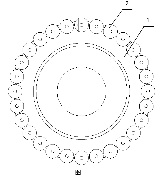
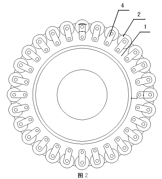
[0029] The present invention as figure 2 , Figure 4 , Figure 5 , Image 6 As shown, the winding disc structure of the steel wire winding machine is mainly composed of a winding disc and 28 sets of wire storage wheel assemblies uniformly fixed on the circumference of the winding disc.

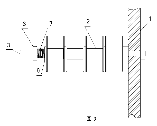
[0030] The wire storage wheel assembly mainly includes a wire storage wheel, a connecting shaft, a splint, a wire storage wheel shaft and a self-locking pin. One end of the connecting shaft is fixedly connected with the winding disc bolts, and 4 pairs of splints are equidistantly arranged at the other end of the connecting shaft. A U-shaped groove is arranged at the center of the shaft at 2 / 3 of the height of the splint, and a self-locking pin hole and a self-locking pin keyway are respectively arranged at both radial ends of the top of the splint. The two ends of the wire storage wheel shaft are provided with bosses that match the U-shaped grooves, and the outer walls of both ends of the...


PUM


Abstract

The invention discloses a winding disc structure of a steel wire winding machine, which mainly comprises a winding disc, and a plurality of groups of steel wire storage wheel assemblies which are uniformly and fixedly arranged on the periphery of the winding disc. Each steel wire storage wheel assembly mainly comprises steel wire storage wheels, a connecting shaft, clamp plates, steel wire storage wheel shafts and self-lock pins. One end of the connecting shaft is fixedly connected with the winding disc through a bolt; the clamp plates are pairwise arranged at the other end of the connecting shaft at equal intervals; the center of the connecting shaft, at 2 / 3 height of each clamp plates, is provided with a U-shaped groove; and a self-lock pin clamping hole and a self-lock pin key slot are respectively arranged at two radial ends of the upper end part of each clamp plate. Bosses matched with the U-shaped grooves are arranged at two ends of the steel wire storage wheel shafts; axial key slots are arranged on outer walls of the two ends of the steel wire storage wheel shafts; the steel wire storage wheels are rotationally sheathed on the steel wire storage wheel shafts; and the steel wire storage wheel shafts and the clamp plates are mutually and movably connected in a concavo-convex inserting way. The winding disc structure can improve the labor productivity by more than ten times, and can guarantee the product quality of tubular products.

Description

technical field [0001] The invention relates to a winding machine, in particular to a winding disc structure of a steel wire winding machine. [0002] It is mainly used to strengthen composite pipe steel wire winding machinery. Background technique [0003] Reinforced composite pipes are widely used in electric power, coal, petroleum, chemical and building materials industries. To produce reinforced composite pipes, especially steel wire wound reinforced layer composite pipes, steel wire winding machine is one of the main equipment. [0004] In the prior art, the steel wire winding machine has the following disadvantages due to the irrationality of the structure design of the winding disc: [0005] 1. There are multiple groups of wire storage wheel assemblies installed on the circumference of the winding disc. Each set of wire storage wheel assemblies is equipped with several wire storage wheels. The installation structure of several wire storage wheels is set in s...

Claims


Application Information

Patent Timeline
Patent Type & Authority Applications(China)
IPC IPC(8): B65H81/06
Inventor 刘海鹰仲宝付
Owner JIANGSU SHENSHI NEW MATERIAL TECH
Why Eureka
Try Eureka