
Folding type electric lifting table

A lifting table and folding technology, applied in the field of folding electric lifting tables, can solve the problems of troublesome opening and installation or dismantling and folding process, easy dislocation, difficult to accurately align, etc., and achieves novel and unique opening or folding methods. , to ensure stability and reliability, to avoid the effect of interference or limitation

Active Publication Date: 2021-12-31
LOCTEK ERGONOMIC TECH CORP
View PDF13 Cites 2 Cited by
  • Summary
  • Abstract
  • Description
  • Claims
  • Application Information

AI Technical Summary

Problems solved by technology

[0003] But the folding electric lifting table of the above prior art still has the following deficiencies: 1. It is necessary to manually pull the lifting column to open and install or disassemble and fold, such as In the process of opening or folding, it is necessary to loosen the screw nut or unlock the lock, etc., then make the column stand upright or lie down, then tighten or loosen the screw nut, or lock or unlock the lock, open and install or disassemble and fold The process is relatively cumbersome and takes a long time, and its operation is relatively cumbersome, time-consuming and laborious, and it still falls into the traditional installation method, and the customer experience is poor
2. Since the customer is not a professional, it is bound to be difficult to align accurately during the opening and installation process, and it is also easy to be misaligned when turning the angle of 180°, which sometimes causes interference or restrictions on the lifting column and affects the normal operation of the electric lifting table

Method used


Image

  • Folding type electric lifting table
  • Folding type electric lifting table
  • Folding type electric lifting table

Examples


Embodiment Construction

[0024] The specific embodiments of the present invention will be further described below in conjunction with the accompanying drawings. What needs to be declared here is that the descriptions of these specific implementations are used to help understand the present invention, but are not intended to limit the present invention. In addition, the technical features involved in the various specific embodiments of the present invention described below may be combined with each other as long as they do not constitute conflicts with each other.

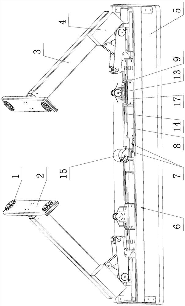
[0025] Such as figure 1 , figure 2 , image 3 , Figure 4 , Figure 5 , Figure 6 , Figure 7 , Figure 8 shown.

[0026]The folding electric lifting table of the present invention comprises a table frame 6 and two lifting columns 3 located at two ends of the table frame 6, and also includes a table board 5, and the table frame 6 and the table board 5 are generally fixed by screws. Table frame 6 and table board 5 all are very ripe...


PUM


Abstract

The invention discloses a folding type electric lifting table which comprises a table frame and two lifting stand columns located at the two ends of the table frame, the top ends of the two lifting stand columns are hinged to the table frame, an electric driving mechanism used for stretching and folding the stand columns is arranged on the table frame, and the electric driving mechanism is connected with two linear reciprocating mechanisms. The movable part of each linear reciprocating mechanism is hinged to the inner end of a connecting rod mechanism, and the outer end of the connecting rod mechanism is hinged to the top end of a lifting stand column so as to drive the lifting stand column to be switched between a horizontal state and a vertical state around a first hinged shaft; for example, a motor for stretching and folding the stand column is arranged in the middle of the length of the table frame, a motor shaft is connected with two lead screws which are rotatably matched on the table frame through a transmission mechanism, a lead screw nut is screwed on each lead screw, each lead screw nut is connected with a hinge seat which is slidably matched on a guide rail, and the hinge seat is hinged with the inner end of the connecting rod mechanism through a second hinge shaft. The folding type electric lifting table is easy and convenient to open and fold, time-saving, labor-saving and rapid.

Description

technical field [0001] The invention relates to the technical field of intelligent furniture, in particular to a folding electric lifting table. Background technique [0002] Electric lift tables occupy more and more important positions in people's work, study and life. In order to reduce the volume of the electric lifting table during transportation and storage, etc., in order to save transportation and storage costs, etc., in recent years, there have been many folding electric lifting tables, which are folded during transportation and storage. The column is opened to a state of 90° to the desktop and the feet of the column are on top, and then the entire table is turned over so that the feet of the two lifting columns land on the ground to be in use. [0003] However, the folding electric lifting table of the prior art still has the following deficiencies: 1. It is necessary to manually pull the lifting column to open and install or disassemble and fold, as in the process...

Claims


Application Information

Patent Timeline
IPC IPC(8): A47B3/08A47B9/20
CPCA47B3/08A47B9/20A47B2003/0824A47B2200/0051A47B2200/0057A47B2200/0062
Inventor 项乐宏林涛张赞封迪庆李方圆
Owner LOCTEK ERGONOMIC TECH CORP
Learn More