
Novel positioning compensation method for PCB by single vision camera

A compensation method and a single-camera technology, applied to measuring devices, instruments, and optical devices, can solve the problems that the mechanical positioning accuracy cannot meet customer requirements, and achieve the effects of improving competitive advantages, high precision, and convenient use

Inactive Publication Date: 2013-01-09
上海功源电子科技有限公司
View PDF4 Cites 15 Cited by
  • Summary
  • Abstract
  • Description
  • Claims
  • Application Information

AI Technical Summary

Problems solved by technology

[0012]3. With the continuous development of technology and the continuous updating of processing equipment, CNC is widely used, which makes the era of relying on imported foreign machines gradually far away. In some high-tech and high-precision industries, higher requirements are put forward for marking technology. Requirements, the pure mechanical positioning accuracy can no longer meet the customer's requirements, the CAS positioning compensation method, for the laser processing system came into being in the application of laser marking for high-end PCB customers

Method used


Image

  • Novel positioning compensation method for PCB by single vision camera
  • Novel positioning compensation method for PCB by single vision camera
  • Novel positioning compensation method for PCB by single vision camera

Examples


Embodiment Construction

[0029] one. basic method:

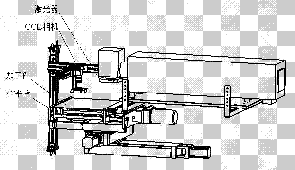
[0030] 1, Basic guarantee: We guarantee that the machine table should have assembly relationship and precision, and the linear drive of motion. Such as: the right angle of the XY platform, the installation of the laser is correct (including the level and parallel to the platform). For specific methods, refer to technical documents: and

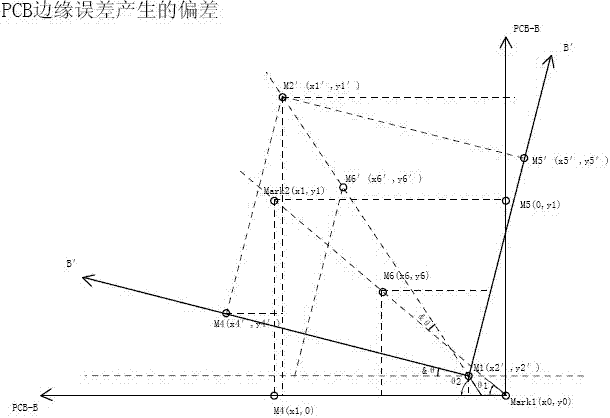
[0031] 2. Compensation improves accuracy: The calculation method of CCD compensation is scientific and reasonable. Currently: a single camera captures two to three positioning points, calculates the current position of the board, and makes compensation.

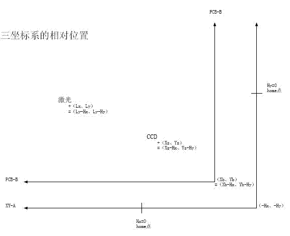
[0032] (1). Coordinate system learning: The machine has three basic coordinate systems, one is the XY-A platform, the other is the base map of the PCB-B board, and the third is the graphic position of the laser L-C. CCD is a fixed eye position (Xz, Yz) in the A coordinate system, such as image 3 shown.

[0033] (2). Compensation method:

[0034] a. As ...


PUM


Abstract

The invention relates to a novel positioning compensation method for a PCB (printed circuit board) of a single vision camera. The novel positioning compensation method mainly aims at PCB positioning. The positioning compensation method comprises the following steps of: detecting a center of a mark point of a product by a CCD (charge coupled device) camera, sending detecting data to a personal computer (PC); calculating a position difference between detected images by using a CCD alignment system (CAS) and recording a corresponding detecting result, thereby obtaining a position offset value; transmitting the result to a computer connected with a laser controller to perform automatic position compensation and correction marking. Compared with a conventional PCB positioning technique, the novel positioning compensation method has the advantages of low cost, convenience in use, high precision and the like; and furthermore, the novel positioning compensation method can support great majority of lasers in the market, the single vision camera can be mounted on an ordinary machine table, and therefore, possibility is provided for product upgrade and application upgrade of customers.

Description

technical field [0001] The invention is a novel CCD single camera position compensation method for PCB. The invention can be applied to the CAS-assisted alignment compensation system (CCD Alignment system, hereinafter referred to as CAS), which is a position compensation system based on the XY coordinate platform and the camera CCD-assisted image positioning. Due to the processing and molding process of PCB It is determined that the position uncertainty of the outer edge and image of each batch and each PCB, high-precision positioning requires the use of CCD for position compensation. This invention belongs to the field of detection technology in opto-mechanical integration. [0002] It uses the CCD camera to determine the XY coordinate system of the PCB, to define and check the pattern and logo of the product, compare the characteristic value of the pattern to be detected, and shift the image to the technical result, using the CAS auxiliary alignment compensation system softw...

Claims


Application Information

Patent Timeline
Patent Type & Authority Applications(China)
IPC IPC(8): G01B11/00
Inventor 卢冬青
Owner 上海功源电子科技有限公司
Learn More