Transformers for Isolation Amplifiers

A technology for isolation amplifiers and transformers, applied in the field of transformers, can solve problems such as failure to meet product electrical performance requirements, small isolation voltage, large coupling capacitance, etc., and achieve the effects of satisfying balanced and symmetrical performance, reducing magnetic flux leakage, and low cost

Active Publication Date: 2015-09-16
WUXI TIANHE ELECTRONICS +1
View PDF7 Cites 0 Cited by
  • Summary
  • Abstract
  • Description
  • Claims
  • Application Information

AI Technical Summary

Problems solved by technology

The applicant of this patent encountered a difficult problem in the manufacture of transformers during the trial production of transformer-coupled isolation amplifiers, because the user requested that the volume of the transformer-coupled isolation amplifiers trial-produced by the applicant for this patent be greatly reduced, and only one transformer could be used. Power and signal transmission must be completed at the same time. It is required that the demodulation winding in the signal transmission transformer has good symmetry and consistency. If the existing two-wire parallel winding structure is adopted, the symmetry and consistency between the windings meet the requirements, but the The coupling capacitance between two windings is too large, and the isolation voltage is too small to meet the electrical performance requirements of the product. Therefore, the ordinary double-wire parallel winding structure cannot meet the above requirements of using a transformer.

Method used


Image

  • Transformers for Isolation Amplifiers
  • Transformers for Isolation Amplifiers
  • Transformers for Isolation Amplifiers

Examples


Embodiment Construction

[0030] The specific implementation manner of the present invention will be described below in conjunction with the accompanying drawings.

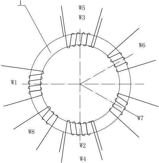
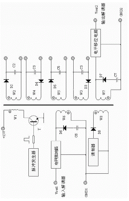
[0031] Such as figure 1 As shown, the present invention includes a toroidal magnetic core 1, and the toroidal magnetic core 1 is wound with a primary winding W1 and a secondary winding:

[0032] See figure 2 , the primary winding W1, its same-named end is connected to a DC voltage source (15V), the opposite-named end of the primary winding W1 is connected to the collector of the switching transistor T, the base of the switching transistor T inputs a pulse voltage, and the switching transistor T’s Emitter grounded;

[0033] The secondary windings include the second power supply winding W2 to the fifth power supply winding W5, the first demodulation winding W6, the second demodulation winding W7 and the modulation winding W8;

[0034] The second power supply winding W2 to the fifth power supply winding W5 are respectively connected to th...


PUM


Abstract

The invention relates to a transformer for an isolation amplifier, which comprises a circular magnetic core wound with a primary side winding and a secondary side winding, wherein the same end of the primary side winding is connected with a direct current voltage source and the different end of the primary side winding is connected with a switching triode. The secondary side winding comprises four power supply windings, two demodulation windings and a modulation winding. The four power supply windings are respectively connected with a rectification circuit. When the switching triode is turned on, a power transmission cycle is started. When the switching triode is turned off, a signal transmission cycle is started so that the transformer for the isolation amplifier has two functions, i.e. power transmission and signal transmission. The primary side winding is coupled with the power supply windings to transmit power and the primary side winding is coupled with the demodulation windings to transmit signals. The transformer for the isolation amplifier has the advantages of small coupling capacitance, large isolation voltage, small leakage inductance and size and the like.

Description

technical field [0001] The invention relates to electronic components, in particular to a transformer suitable for isolation amplifiers. Background technique [0002] The isolation amplifier is an amplifier connected to the electrical insulation between the input circuit and the output circuit. It uses a transformer or optical coupling to transmit signals. It is widely used in various aspects such as industrial control, signal measurement, medical equipment, and signal amplification. The function of the isolation amplifier is to isolate the analog signal and amplify it according to a certain ratio. The output signal distortion is required to be small, and the parameters such as linearity, accuracy, bandwidth, and isolation withstand voltage must meet the requirements for use. [0003] In general, transformers are used as a single function: one function is to transmit power, which is classified as a power transformer; the other function is to transmit signals and achieve elec...

Claims


Application Information

Patent Timeline
Patent Type & Authority Patents(China)
IPC IPC(8): H01F30/16H01F27/40
Inventor 刘盘泉陈文卿奚建勇梁继远张爱学
Owner WUXI TIANHE ELECTRONICS
Why Eureka
Try Eureka