Special rack drive traverse unit

A technology of rack drive and wire arranging device, which is applied in the field of wire drawing unit mechanism, can solve problems such as screw wear, cylinder body piston easy wear, high air clamp failure rate, etc., achieve uniform reciprocating motion left and right, improve stability and reliability, and discharge The effect of high line precision

Active Publication Date: 2014-08-20
江苏泰隆机电科技有限公司
View PDF8 Cites 0 Cited by
  • Summary
  • Abstract
  • Description
  • Claims
  • Application Information

AI Technical Summary

Problems solved by technology

[0002] At present, the wire arranging mechanism adopted by the domestic wire drawing machine take-up machine specifically includes the following four structures: 1. Two-way screw wire arranging device. This kind of mechanism has a constant row spacing and row width. When changing, the row spacing and row width cannot be adjusted; 2. Polished rod cable arrangement, the row spacing and row width of this mechanism can be adjusted, but when the equipment is running at a high speed, due to the heavy weight of the polished rod cable arrangement, it is on the left and right When reversing, due to inertia, it is easy to cause hysteresis, so that when the I-shaped wheel is rewound at a high speed, it is easy to cause the piled wires at both ends to bulge, so it is not suitable for precision wiring; The line spacing and row width of this mechanism can be adjusted, but because the O-ring seal is used in the splint, and the cylinder suction frequency is fast in actual work, the O-ring and the piston of the cylinder body are easy to wear, so this kind of The air clamp failure rate of the mechanism is high, and the production workshop must be equipped with an air compressor station for air supply, and the cost of use is high; 4. The servo motor cooperates with the ball screw cable arrangement. The row spacing and row width of this mechanism are adjustable, and the cable arrangement accuracy High, but the ball screw needs to be produced by a professional manufacturer, which is expensive, and at the same time has high requirements for the production environment, otherwise the dust will easily cause the screw to wear and fail, and it will be troublesome to disassemble when replacing the screw

Method used


Image

  • Special rack drive traverse unit
  • Special rack drive traverse unit
  • Special rack drive traverse unit

Examples


Embodiment Construction

[0016] The present invention will be further described below in conjunction with embodiment.

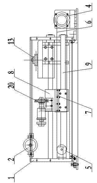
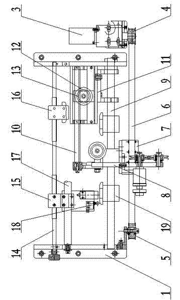
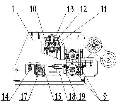
[0017] Figure 1-3 As shown, a rack drive special cable arrangement includes a frame 1, a guide wheel 2, a servo motor 3, a driving pulley 4, a passive pulley 5, a flat belt 6, a splint 7, a cable pulley frame 8, and a slide bar 9. Movable rack 10, fixed rack 11, gear shaft 12, cable pulley 13, adjusting screw 14, left travel switch fixed plate 15, right travel switch fixed plate 16, adjustment slide bar 17, travel switch 18, touch plate 19 and guide wheel 20. Frame 1 is provided with sliding rod 9 parallel to each other, adjusting screw rod 14 and adjusting sliding rod 17. One side of frame 1 is provided with servo motor 3. Servo motor 3 is connected to the frame through driving pulley 4 and flat belt 6. 1 The passive pulley 5 on the other side, the flat belt 6 is parallel to the slide bar 9, the flat belt 6 is connected with a splint 7 through screw locking, and the splint 7 is c...


PUM


Abstract

The invention relates to a special rack drive traverse unit which is mainly used for the field of metal product wire processing. The special rack drive traverse unit integrally and structurally comprises a servo motor, a synchronous belt and a gear, the servo motor and the flat belt match with travel switches to drive a traversing wheel carrier to reciprocate, so that a movable rack and a fixed rack are jointly meshed with a gear shaft to achieve rotational traversing of a traversing wheel on the gear shaft. The special rack drive traverse unit is capable of meeting requirements of traversing on various adjustments of traverse lay and traverse width, high in traversing precision, convenient to operate and maintain and low in manufacturing and operating cost, has no special requirements on production environments and does not need an air compression station.

Description

technical field [0001] The invention relates to a wire drawing unit mechanism, in particular to a rack drive special wire arranging device used for wire arranging when the wire drawing unit is taken up. Background technique [0002] At present, the wire arranging mechanism adopted by the domestic wire drawing machine take-up machine specifically includes the following four structures: 1. Two-way screw wire arranging device. This kind of mechanism has a constant row spacing and row width. When changing, the row spacing and row width cannot be adjusted; 2. Polished rod cable arrangement, the row spacing and row width of this mechanism can be adjusted, but when the equipment is running at a high speed, due to the heavy weight of the polished rod cable arrangement, it is on the left and right When reversing, due to inertia, it is easy to cause hysteresis, so that when the I-shaped wheel is rewound at a high speed, it is easy to cause the piled wires at both ends to bulge, so it ...

Claims


Application Information

Patent Timeline
Patent Type & Authority Patents(China)
IPC IPC(8): B21C47/10
Inventor 李辉
Owner 江苏泰隆机电科技有限公司
Why Eureka
Try Eureka