
Optimal design method for parameter of controllable cylinder type hydraulic buffer of semi-active suspension

A technology of semi-active suspension and hydraulic shock absorber, applied in the direction of shock absorber, shock absorber, spring/shock absorber, etc. , reliable design method, lack of accurate design mathematical model of shock absorber valve parameters, etc., to avoid repeated tests and modifications, shorten the development cycle, and achieve accurate and reliable design values.

Inactive Publication Date: 2012-12-26
SHANDONG UNIV OF TECH
View PDF2 Cites 32 Cited by
  • Summary
  • Abstract
  • Description
  • Claims
  • Application Information

AI Technical Summary

Problems solved by technology

Although scholars in our country have done a lot of research on this, there is still no accurate calculation and analysis formula for valve plate design for controllable cylinder hydraulic shock absorber valve parameters, lack of accurate and reliable design methods, and lack of vibration reduction methods. The mathematical model for precise design of damper valve parameters seriously restricts the optimal design of controllable cylinder hydraulic shock absorber valve parameters, which is inconsistent with the current development trend of automobiles

Method used

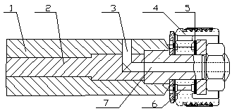

Image

  • Optimal design method for parameter of controllable cylinder type hydraulic buffer of semi-active suspension
  • Optimal design method for parameter of controllable cylinder type hydraulic buffer of semi-active suspension
  • Optimal design method for parameter of controllable cylinder type hydraulic buffer of semi-active suspension

Examples


Embodiment Construction

[0032] The present invention will be further described in detail through an embodiment below.

[0033] The sprung mass of an automobile suspension system m 2 =445kg; unsprung mass m 1 =38kg; suspension spring stiffness K =29679N / m and tire stiffness K t =267112N / m; shock absorber installation leverage ratio i =0.95; shock absorber installation angle θ =5°; the annular area between the piston cylinder and the piston rodS r =3.02×10 -4 m 2 ;Cylinder inner diameter D H =28mm; piston gap length L H =9mm; Piston average clearance δ H =0.04mm; eccentricity e =1.0; oil dynamic viscosity mu t =8.9×10 -3 m 2 Ps; oil density ρ =0.89×10 3 kg / m 3 ;Number of piston holes n h =4; piston hole diameter d h =2mm; equivalent length of piston hole L he =5mm; normally open orifice area A 0 =0.2mm 2 ;Normally throttling orifice flow coefficient ε 0 =0.82; adjustable damping orifice flow coefficient ε v =0.82; equivalent length of piston rod hole L ge =30...


PUM


Abstract

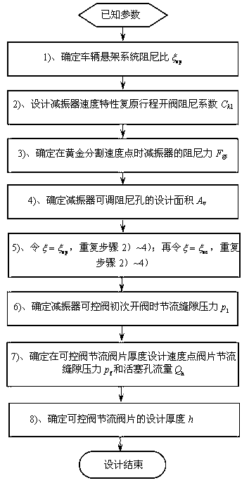
The invention relates to an optimal design method for a parameter of a controllable cylinder type hydraulic buffer of a semi-active suspension. The optimal design method is characterized by adopting the following steps: 1), determining the damping ratio of a vehicular suspension system; 2), designing an open valve damping coefficient of a buffer speed property recover route; 3), determining the damping force of the reducer at a golden cutting speed point; 4), determining the design area of an adjustable damping hole of the reducer; 5), repeating the steps 2) to 4), calculating the adjustable damping hole area required by the thickness of the design valve block is calculated; repeating the steps 2) to 4) again, and calculating the minimum area of the adjustable damping hole; 6), determining the throttle seam pressure when a controllable valve of the buffer is opened at the first time; 7), determining the throttle seam pressure and the piston hole flow rate at the thickness designed speed point of the controllable valve throttle valve block; 8), determining the design thickness of the controllable valve throttle valve block. By adopting the design method, the design value of the valve parameter is exact and reliable; the repeatedly test and modification are avoided; the design cost of the controllable buffer is reduced; and the development cycle of the buffer is shortened.

Description

technical field [0001] The invention relates to a semi-active suspension of an automobile, in particular to a design method for a controllable valve parameter of a controllable cylinder hydraulic shock absorber of the semi-active suspension. Background technique [0002] The controllable shock absorber of automobile semi-active suspension is the most widely used controllable cylinder hydraulic shock absorber, and its damping characteristics are mainly determined by the parameters of the shock absorber valve. At present, there is no accurate and reliable design method for the valve parameter design of the controllable cylinder hydraulic shock absorber at home and abroad. Reliable shock absorber design technology. Although scholars in our country have done a lot of research on this, there is still no accurate calculation and analysis formula for valve plate design for controllable cylinder hydraulic shock absorber valve parameters, lack of accurate and reliable design methods...

Claims


Application Information

Patent Timeline
Patent Type & Authority Applications(China)
IPC IPC(8): F16F9/34
Inventor 周长城赵雷雷毛少坊
Owner SHANDONG UNIV OF TECH
Learn More