
Node Connector Component

A technology of node connectors and connectors, which is applied in the direction of vehicle connectors, connections, parts of connection devices, etc., can solve problems such as deterioration, damage, and increase in quantity, so as to reduce volume, prevent damage, and not reduce durability sexual effect

Inactive Publication Date: 2015-11-25
TYCO ELECTRONICS AMP KOREA
View PDF7 Cites 0 Cited by
  • Summary
  • Abstract
  • Description
  • Claims
  • Application Information

AI Technical Summary

Problems solved by technology

[0007] In the above configuration, the arrangement of various power supply wires 721, 723, 725 connected to the front and rear areas of the car is very complicated in the limited and narrow space of the car, and as a result, the assembly efficiency of connectors and wires deteriorates
[0008] Additionally, when a tool is used to install the connector mechanism, various wires can be damaged due to frictional contact with the tool or being folded to one side to provide room for the tool to operate
[0009] In addition, the structural constraints of the car are such that multiple wires should be installed at the same location and bent sharply, so damage to the wires due to layout fatigue is inevitable
[0010] Also, mounting multiple wires in the same location exacerbates damage due to frictional contact between the wires
[0011] At the same time, if Figure 8B As shown, the connector 710 should be inserted through the installation hole 701 perforated in the vehicle body frame panel 700, and a separate member for covering the installation hole 701 is required, thereby causing an increase in the number of installation processes and the vehicle body frame panel 700 The strength of the deterioration

Method used


Image

  • Node Connector Component
  • Node Connector Component
  • Node Connector Component

Examples


Embodiment Construction

[0046] Hereinafter, exemplary embodiments of the present invention will be described in more detail with reference to the accompanying drawings.

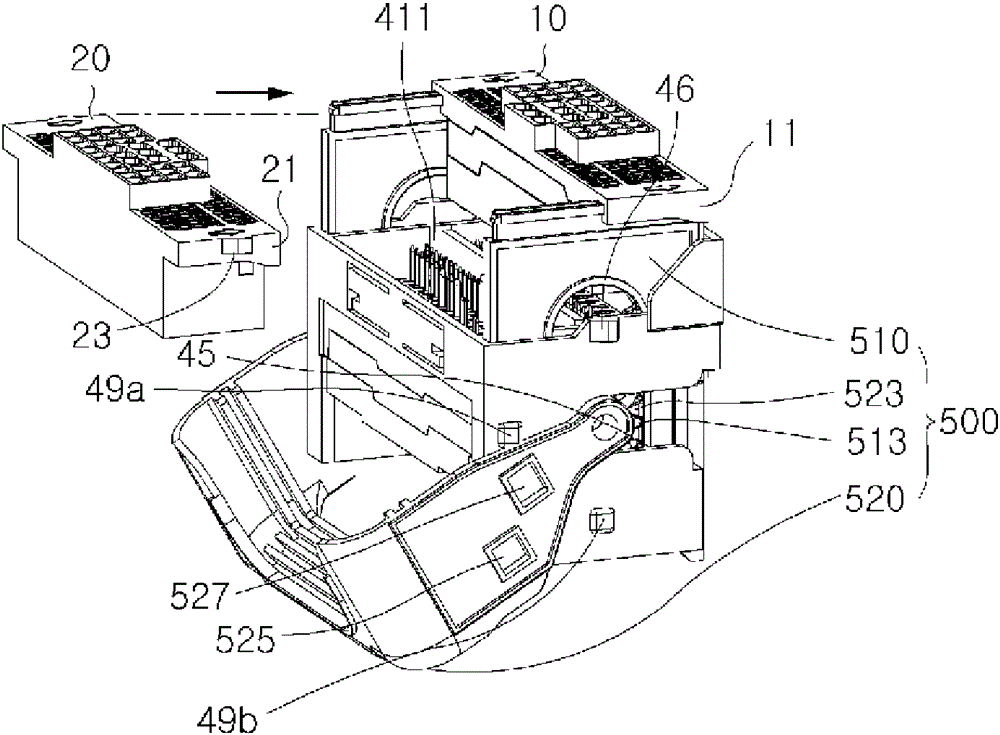
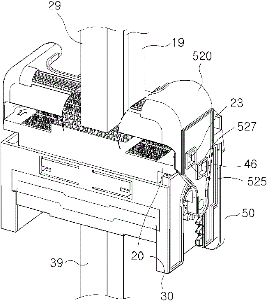
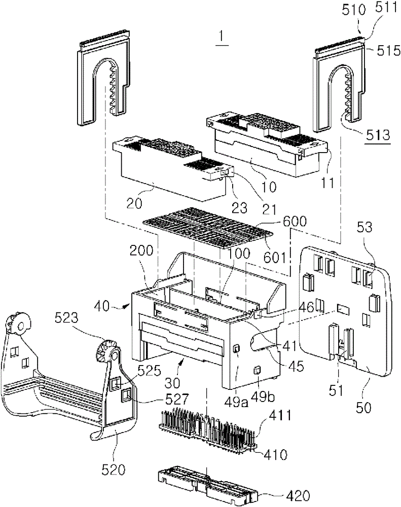
[0047] figure 1 is a diagram schematically showing the electrical connection of a node connector according to the present invention, figure 2 is an exploded perspective view of a node connector assembly according to the present invention, and, image 3 is an exploded perspective view showing the coupling relationship of a circuit board and a covering member included in the node connector assembly according to the present invention.

[0048] As shown in the figure, the node connector of the present invention includes a plurality of connectors, for example, a first connector 10 , a second connector 20 and a third connector 30 electrically connected to each other. The first connector 10 and one of the third connectors 30 are directly connected to each other via their first connection terminal 10' and one third connection terminal 30'...


PUM


Abstract

The invention relates to a joint connector assembly including first and second connectors connected to each other by a circuit board and connected to third connectors by connection terminals. The circuit board is mounted at the center of the third connectors below the first and second connectors located in an upper region of a main body housing and is integrally formed with the main body housing in a lower region thereof. The upper region of the main body housing defines first and second connector receptacles for the first and second connectors. A cover member is attached to a lower surface of the circuit board to cover the circuit board. The joint connector assembly has a reduced volume because the connectors are connected to one another without lines and all the connectors are inserted in the main body housing, allowing the joint connector assembly to be installed in a small space.

Description

technical field [0001] The present invention relates to joint connectors, and more particularly to joint connector assemblies in which a plurality of connectors are electrically connected to each other via direct contact of circuit boards and connection terminals, rather than using multiple joint connectors. connection wires, and all these constituent elements are mounted to the main body case. Background technique [0002] In general, a connector composed of a connector housing and connection terminals is widely used, for example, in power circuits of washing machines, refrigerators, and automobiles. When such connectors are applied to electrical and electronic appliances, individual elements can be assembled with each other in advance, and then the finished assembly can be inserted into the final product, as a result, maintenance, repair and production of the aforementioned appliances are significantly simplified. [0003] In the case where one connector is to be coupled ...

Claims


Application Information

Patent Timeline
Patent Type & Authority Patents(China)
IPC IPC(8): H01R12/70H01R13/629
CPCH01R13/514H01R12/716H01R13/62944H01R13/6658H01R2201/26
Inventor 李喆燮
Owner TYCO ELECTRONICS AMP KOREA
Learn More