Eureka AIR delivers breakthrough ideas for toughest innovation challenges, trusted by R&D personnel around the world.

Gas distributor for ash agglomerating fluidized-bed gasification furnace

A gas distributor and gasifier technology, applied in the direction of granular/powdered fuel gasification, etc., can solve the problems that the shell is difficult to meet the long-term operation, the material requirements of the central tube are high, and the outer wall of the central tube is worn, etc., to achieve Conducive to large-scale production, lower temperature resistance requirements, and longer service life

Inactive Publication Date: 2012-12-19
SHANDONG TIANLI DRYING TECH & EQUIP
View PDF12 Cites 8 Cited by
  • Summary
  • Abstract
  • Description
  • Claims
  • Application Information

AI Technical Summary

Problems solved by technology

[0007] Application No.: 200520079695.3 and 200520105814.8 The disadvantage of the two gas distributors disclosed is that the center pipe of the gas distributor is located in the ring pipe, the outer wall of the center pipe and the inner wall of the ring pipe form a ring channel, and the ash in the gasifier passes through the ring pipe. The channel is discharged out of the furnace, so the air scour and slag discharge under high temperature conditions cause serious wear on the outer wall of the central tube, which requires high material prices for the central tube
However, the high-temperature material directly contacts the shell and fluidizes on it. The shell must bear the high temperature and at the same time bear the friction with the material. It is difficult for the shell to meet the requirements of long-term operation.
In addition, the gas distributors of these two structures design the bottom of the gasifier into a conical structure, and the gasifier at the conical bottom restricts the application of pressure in the gasification process

Method used


Image

  • Gas distributor for ash agglomerating fluidized-bed gasification furnace
  • Gas distributor for ash agglomerating fluidized-bed gasification furnace
  • Gas distributor for ash agglomerating fluidized-bed gasification furnace

Examples


Embodiment Construction

[0038] The present invention will be described in detail below in conjunction with the accompanying drawings and embodiments.

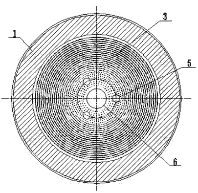
[0039] see figure 1 , figure 2 , Embodiment 1 of the present invention is a specific implementation mode provided with four distributed injection pipes 5, such as figure 1 and figure 2 As shown, the structure of the gas distributor includes gasifier shell 1, dense phase zone 2, conical distribution plate 3, distribution plate fluidization hole 4, distributed injection pipe 5, slag discharge pipe 6, injection pipe inlet Gas pipe 7, air chamber inlet pipe 8, air chamber 9 and slag discharge pipe inlet pipe 10. The conical distribution plate 3 is sealed and fixed on the casing 1 of the gasifier, see Figure 6 , the conical distribution plate 3 is provided with several axial fluidization holes 4 in the horizontal direction, the opening ratio of the fluidization holes 4 is 0.4-0.65%, and the diameter of the fluidization holes 4 is 1-3mm. The above-me...


PUM

PropertyMeasurementUnit
diameteraaaaaaaaaa
porosityaaaaaaaaaa
porosityaaaaaaaaaa

Abstract

The invention provides a gas distributor for an ash agglomerating fluidized-bed gasification furnace. The gas distributor comprises a gasification furnace shell, a tapered distribution plate, at least three distributed injection pipes, a slagging pipe and a gas inlet pipe of a gas chamber, wherein one end of the slagging pipe is connected to the bottom of the tapered distribution plate, and is open, and the other end of the slagging pipe penetrates through the gasification furnace shell, and is connected with a gasification agent gas source. The gas distributor is characterized in that one end of each distributed injection pipe is connected to the lower part of the tapered distribution plate, and is open, and the other end of each distributed injection pipe penetrates through the gasification furnace shell, and is connected with the gasification agent gas source; and openings of the distributed injection pipes in the tapered distribution plate are symmetrically and uniformly distributed about the center of the slagging pipe. The gas distributor is high in fluidization performance, adapted to long-cycle running, simple in structure and applicable to a large-sized fluidized-bed gasification furnace.

Description

technical field [0001] The invention relates to a gas distributor, in particular to a gas distributor for an ash fusion agglomeration fluidized bed gasification furnace. Background technique [0002] Gasification is the main way to efficiently and cleanly convert primary energy such as coal and biomass into secondary energy such as gas. Coal gas can not only generate electricity through the gas-steam combined cycle, but also can be used to manufacture high-value chemical products, such as synthetic ammonia, methanol, etc., to realize a polygeneration energy system that jointly produces electricity, clean energy and high value-added chemical products. Therefore, gasification not only solves the pollution problem in the direct combustion process, but also can form high-value products, which occupies a very important position in my country's energy strategy. At present, gasification technology at home and abroad is developing towards large-scale, which can increase the product...

Claims


Application Information

Patent Timeline
Patent Type & Authority Applications(China)
IPC IPC(8): C10J3/56
Inventor 范红梅姜荣泉黄贤具曹明见曹世峰宋学凯史雷王雪
Owner SHANDONG TIANLI DRYING TECH & EQUIP
Why Eureka
Eureka Blog
Learn More