
Sliding hydrofoil boat for preventing sliding surface from splashing

A sliding surface and wing skid technology, which is applied in the field of wing skids and high-performance ships, can solve the problems of strict weight distribution, impact on economy, serious impact, etc., to improve impact and course stability, and comprehensive technical and economic performance Excellent, the effect of overcoming inflexibility

Inactive Publication Date: 2015-07-22
JIANGSU UNIV OF SCI & TECH
View PDF7 Cites 0 Cited by
  • Summary
  • Abstract
  • Description
  • Claims
  • Application Information

AI Technical Summary

Problems solved by technology

Compared with conventional displacement ships, its advantage is fast speed, and its disadvantages are large vibration, severe impact, poor course stability, and strict weight distribution requirements. This shortcoming seriously limits the weight of the boat.
When the planing boat or hydrofoil sails at high speed, the splash is large, which consumes part of the power of the main engine and affects its economy
When the hydrofoil boat sails at high speed on the water surface, it relies on the water lift generated by the hydrofoil to completely lift the hull out of the water. Under the same displacement and propulsion power, its speed is more than 15% higher than that of the planing boat. It overcomes many shortcomings of the planing boat. , but it stalls a lot in waves, and the propulsion device is relatively complicated and expensive

Method used


Image

  • Sliding hydrofoil boat for preventing sliding surface from splashing
  • Sliding hydrofoil boat for preventing sliding surface from splashing
  • Sliding hydrofoil boat for preventing sliding surface from splashing

Examples


Embodiment Construction

[0020] The present invention will be further described below in conjunction with drawings and embodiments.

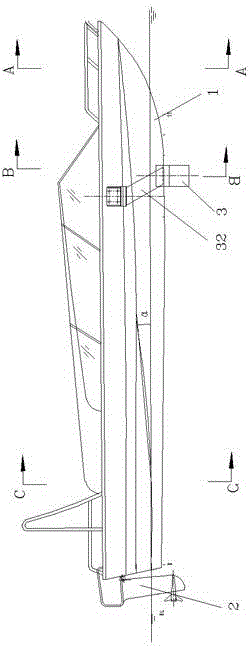
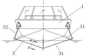
[0021] Such as figure 1 , figure 2 As shown, the present invention includes a hull 1, a propulsion device 2 and a hydrofoil 3 arranged at the front of the hull, and the propulsion device 2 is arranged as follows for hulls 1 of different scales: the length of the hull 1 is 8-9 meters When the propulsion device 2 is less than or equal to 10 meters in length, the propulsion device 2 adopts an outboard engine; when the length of the hull 1 is more than 8-9 meters, an inboard engine full-cavitation propeller or an outboard engine all-cavitation propeller is used; when the hull length is more than 15 meters, except for using In addition to the propulsion of the above two devices, a landline full-cavitation propeller can also be used.

[0022] The cutting hydrofoil 3 includes a horizontal hydrofoil body 31 and several symmetrically arranged pillars 32. The hydrofoil body 31...


PUM


Abstract

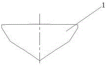
The invention discloses a sliding hydrofoil boat for preventing a sliding surface from splashing. The sliding hydrofoil boat comprises a boat body, a propelling device and paddling hydrofoils, wherein the sliding surface is formed on the bottom surface of the stern part of the boat body. Two sides of the boat body transversely and symmetrically extend from the bilge area of a mid-boat to the incline downside of the stern to form short hydrofoil-shaped bodies, and the short hydrofoil-shaped bodies downwards aslant extend to the stern along the longitudinal direction. The boat body gradually transits to a boat bottom with an improved shallow V-shaped cross section or horizontal cross section of a stern sliding surface gradually from the deep V-shaped cross section of the fore body to the stern. Hydrofoil bodies comprise shallow V-shaped padding hydrofoils, deep-soaking horizontal paddling hydrofoils, trapezoidal paddling hydrofoils and ladder shallow V-shaped padding hydrofoils, and a plurality of kinds of stern sliding surfaces and a plurality of kinds of hydrofoils are combined in pairs to form a plurality of kinds of sliding hydrofoil boats. According to the invention, the defects of large inherent vibration, poor sailing stability and the like of the planing boat or hydrofoil boat are overcome, and the inflexibility of the arrangement of the planing boat is overcome. The short hydrofoil-shaped bodies can effectively prevent the sliding surface from laterally splashing during high-speed sailing.

Description

technical field [0001] The invention relates to a high-performance ship, in particular to a wing-skid boat with the functions of a planing boat and a hydrofoil boat and an anti-splash function on a sliding surface, and belongs to the technical field of high-performance ships. Background technique [0002] Planing boats and hydrofoil boats are important members of the family of high-performance boats. A planing boat that glides on the water at high speed relies on hydrodynamic force to support most of its weight, and water buoyancy only supports a small part of the weight of the planing boat. Compared with conventional displacement ships, its advantage is fast speed, and its disadvantages are large vibration, severe impact, poor course stability, and strict weight distribution requirements. This shortcoming seriously limits the weight arrangement of the boat. When the planing boat or hydrofoil sails at high speed, the splash is large, which consumes part of the power of the m...

Claims


Application Information

Patent Timeline
Patent Type & Authority Patents(China)
IPC IPC(8): B63B1/26
Inventor 杨松林
Owner JIANGSU UNIV OF SCI & TECH
Learn More