Speaker system coupled by low and high sounds of piezoelectric materials and sound vibration device
A technology of sound vibration and piezoelectric material, applied in the field of speaker system, can solve the problems of low sound pressure output, poor sound quality, high harmonic distortion, and achieve the effect of optimized sound quality, low cost, and small external magnetic interference
- Summary
- Abstract
- Description
- Claims
- Application Information
AI Technical Summary
Problems solved by technology
Method used
Image
Examples
Embodiment 1
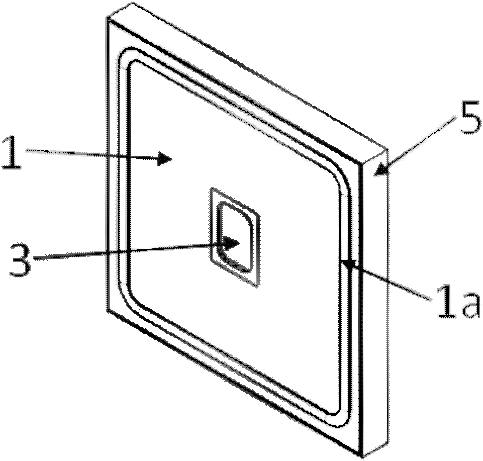
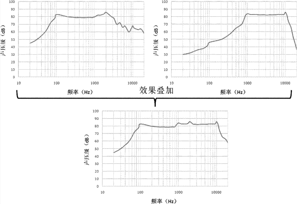
[0037] Fig. 1 (A) and Fig. 1 (B) are the sectional view and the isometric side view along the symmetry plane of Embodiment 1 of the present invention, figure 2 The beneficial effect of Embodiment 1 of the present invention is introduced in the form of a sound pressure frequency response curve diagram. There is a hole in the center of the larger-sized vibrating membrane 1, and a ring structure 1a to improve the bass effect. The diaphragm material is a metal material including nickel-iron alloy, stainless steel, etc., or a polymer material including polyethylene naphthalate fiber (PEN), polyether ketone fiber (PEEK) and the like. The piezoelectric ceramic 2 is bonded to the bottom, which is used to drive the diaphragm 1 to vibrate, mainly for reproducing bass, and the position of the piezoelectric ceramic 2 can adjust the vibration mode of the diaphragm and optimize the sound quality. The shape of the piezoelectric ceramic 2 is a ring or four squares evenly distributed along th...
Embodiment 2
[0039] Fig. 3(A) and Fig. 3(B) are a sectional view and an isometric side view along the plane of symmetry of this embodiment. It differs from Embodiment 1 in that a small-sized piezoelectric speaker 6 is used to replace the small-sized moving coil speaker 3, so that the thickness of the rear cavity 4 can be reduced to no more than 3 millimeters, thereby further ensuring the speaker system of the present invention. The ultra-thin characteristics. Embodiment 2 can also be obtained with figure 2 Similar beneficial mid-bass coupling.
Embodiment 3
[0041]Fig. 4(A) and Fig. 4(B) are a sectional view and an isometric side view along the plane of symmetry of this embodiment. It differs from Embodiment 1 in that it adopts a multifunctional sounding vibration device 7 (MFD) to replace the small-sized moving coil loudspeaker 3 and piezoelectric ceramics 2. The principle and function of the MFD are not the essence of the present invention, so in This will not be described in detail. Among them, the sounding part 7a of the MFD can reproduce the middle and high tones, and the vibrating part of the MFD can drive the large-sized diaphragm 1 to reproduce the bass. This structural design is simpler and more compact without losing the beneficial effect of the present invention. Embodiment 3 can also be obtained with figure 2 Similar beneficial mid-bass coupling.
PUM
 Abstract
Description
Claims
Application Information
 - R&D
- Intellectual Property
- Life Sciences
- Materials
- Tech Scout
- Unparalleled Data Quality
- Higher Quality Content
- 60% Fewer Hallucinations
Browse by: Latest US Patents, China's latest patents, Technical Efficacy Thesaurus, Application Domain, Technology Topic, Popular Technical Reports.
© 2025 PatSnap. All rights reserved.Legal|Privacy policy|Modern Slavery Act Transparency Statement|Sitemap|About US| Contact US: help@patsnap.com


