Antenna and wireless communication device

An antenna and metal substructure technology, which is applied to the antenna grounding device and the structural form of the radiating element, can solve the problems of difficult to meet the system design requirements of low power consumption, increase the design of the electronic system feeder, and increase the area of ​​the radio frequency system.

Inactive Publication Date: 2012-12-05
KUANG CHI INST OF ADVANCED TECH +1
View PDF4 Cites 5 Cited by
  • Summary
  • Abstract
  • Description
  • Claims
  • Application Information

AI Technical Summary

Problems solved by technology

However, the impedance matching network additionally increases the feeder design of the electronic system and increases the area of ​​the radio frequency system. At the same time, the matching network also introduces a lot of energy loss, which is difficult to meet the system design requirements of low power consumption.

Method used


Image

  • Antenna and wireless communication device
  • Antenna and wireless communication device
  • Antenna and wireless communication device

Examples


Embodiment Construction

[0037] The specific content of the present invention will be described in detail below in conjunction with the accompanying drawings.

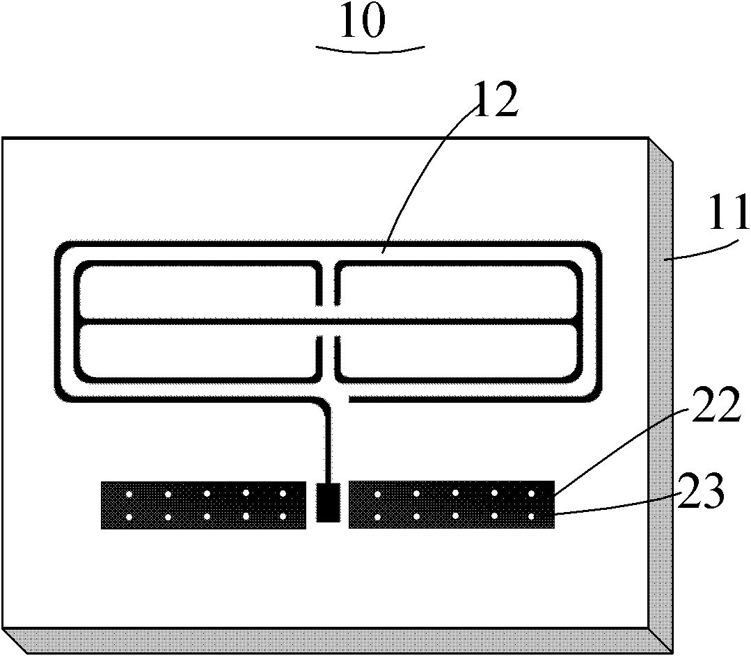
[0038] Please refer to figure 1 , is a perspective view of an embodiment of the antenna of the present invention. The antenna 10 includes a dielectric substrate 11 , a metal structure 12 and a grounding unit 22 all attached to the dielectric substrate 11 . The ground unit 22 is a metal sheet and at least one metallized through hole 23 is opened thereon. In this embodiment, a metal structure 12 is attached to one surface of the dielectric substrate 11 of the antenna 10; a grounding unit 22 is provided on the opposite two surfaces of the dielectric substrate 11, and a grounding unit 22 is provided at the corresponding position of the metalized through hole 23. The solid substrate 11 is also provided with through holes (not shown in the figure), through which the scattered ground units 22 are electrically connected to form a common ground throu...


PUM


Abstract

The invention relates to an antenna, which comprises a medium substrate and a grounding unit which is adhered onto the medium substrate, and the antenna also comprises a metal structure which is adhered onto the medium substrate, the metal structure comprises an electromagnetic response unit, a metal open ring which is arranged surrounding the electromagnetic response unit and a feed point which is connected with the metal open ring, and the electromagnetic response unit comprises an electric field coupling structure. Such design is equivalent to the increase of a physical length of the antenna, a radio frequency antenna which works under an ultra-low working frequency can be designed inside a ultra-small space, so that the physical limitation that the traditional antenna is controlled by the space area when working under the low frequency can be solved, and the miniaturization, low working frequency and broadband multimode requirements of a mobile phone antenna can be met. Simultaneously a design way with lower cost can be provided for the antenna design of a wireless communication device.

Description

technical field [0001] The invention relates to the field of antennas, in particular to an antenna and a wireless communication device using the antenna. Background technique [0002] With the high development of semiconductor technology, higher and higher requirements are put forward for the integration of today's electronic systems, and the miniaturization of devices has become a technical issue of great concern to the entire industry. However, unlike the development of IC chips following "Moore's Law", radio frequency modules, another important component of electronic systems, face the difficult technical challenge of device miniaturization. The radio frequency module mainly includes main components such as frequency mixing, power amplifier, filter, radio frequency signal transmission, matching network and antenna. Among them, the antenna is the radiating unit and receiving device of the final radio frequency signal, and its working characteristics will directly affect t...

Claims


Application Information

Patent Timeline
Patent Type & Authority Applications(China)
IPC IPC(8): H01Q1/38H01Q1/48
Inventor 刘若鹏徐冠雄方能辉
Owner KUANG CHI INST OF ADVANCED TECH
Why Eureka
Try Eureka