Furnace pressure control structure of rotary hearth furnace

A technology of furnace pressure control and rotary hearth furnace, which is applied to furnaces, furnace types, fluidized bed furnaces, etc., can solve the problems of increasing the heat loss of waste gas production, reducing the heat transfer of heated materials, and increasing the heat loss of waste gas, etc., to achieve Effects of clean and green production, improvement of equipment thermal efficiency, and reduction of production costs

Inactive Publication Date: 2012-12-05
LAIWU IRON & STEEL GRP
View PDF4 Cites 2 Cited by
  • Summary
  • Abstract
  • Description
  • Claims
  • Application Information

AI Technical Summary

Problems solved by technology

Since the rotary hearth furnace is a kind of non-sealed thermal equipment, when negative pressure appears at the inlet and outlet or other doors, holes, and holes, the cold air from the outside will be sucked into the furnace to lower the furnace temperature and reduce the transmission to the heated materials. At the same time, the amount of heat generated by the exhaust gas and its heat loss will be increased; when positive pressure appears in these open areas, it will cause the high-temperature furnace gas to escape and cause fire, which will also reduce the heat transfer to the heated material and increase the heat loss of the exhaust gas. , both of these situations will have adverse effects on the thermal process in the furnace

Method used


Image

  • Furnace pressure control structure of rotary hearth furnace
  • Furnace pressure control structure of rotary hearth furnace
  • Furnace pressure control structure of rotary hearth furnace

Examples


Embodiment Construction

[0027] Below in conjunction with accompanying drawing of description, specific embodiment and implementation effect of the present invention will be further described:

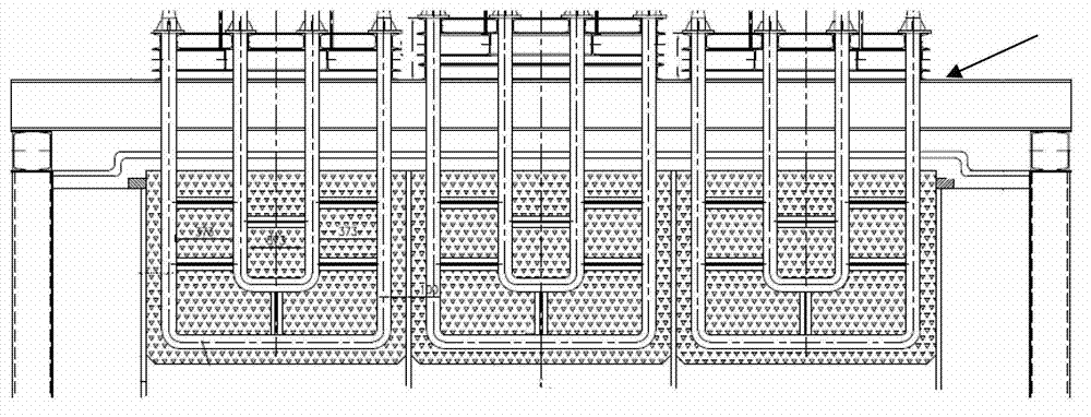
[0028] In the example of the present invention, the rotary hearth furnace has a bottom width of 5m and an effective bottom area of ​​412m 2 . The effective angle of the whole furnace from the feed end to the discharge end is 330°, which is divided into preheating section, reduction I section, reduction II section, soaking section I and soaking section II, and the crossing angles of each section are 53°, 76°, 70°, 65°, 66°, the furnace heights of each section are 1.5m, 2.1m, 1.5m, 1.3m, 1.3m respectively. Since the counterflow of pellets and furnace gas can improve the gas-solid heat exchange efficiency, the furnace smoke outlet is set at the junction of the preheating section and the reduction section I, which are closer to the feed inlet.

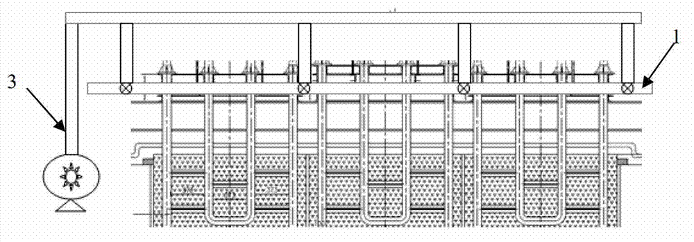
[0029] In order to adjust the furnace pressure distribution in the ...


PUM


Abstract

The invention relates to a furnace pressure control structure of a rotary hearth furnace. A smoke exhaust flue of the rotary hearth furnace is formed at one end close to a feeding hole; one side of the smoke exhaust flue which is deviated to the feeding hole is provided with a retaining wall with adjustable descending amplitude and shielding area for controllably increasing the flow resistance of furnace gas on the same side flowing towards a smoke outlet; and moreover, the incidence directions of a gas burner and a secondary air nozzle between the smoke outlet and a discharging hole are deviated to the air flow direction of a main body furnace, so that the disturbance of gas and secondary air jet current on furnace gas flow is relieved, the flowing resistance and pressure drop are reduced, and the furnace gas flow resistance and pressure drop on both sides of the smoke outlet and the furnace pressure close to the discharging hole are balanced by adjusting the descending scale of the retaining wall on the basis of controlling the entire furnace pressure level in the furnace by adjusting a baffle plate of the smoke exhaust flue. Due to the adoption of the furnace pressure control structure, the furnace pressure distribution in the furnace length direction of the rotary hearth furnace can be improved effectively, zero pressure or slight positive pressure control is realized simultaneously on feeding and discharging holes, the energy consumption of equipment is lowered effectively, pellet quality is improved, environmental pollution is lowered, and clean production is realized.

Description

technical field [0001] The invention belongs to the technical field of production of metallized pellets (or direct reduced iron) in the iron and steel industry, and in particular relates to a furnace pressure control structure of a rotary hearth furnace, so as to realize the furnace pressure control of the rotary hearth furnace. Background technique [0002] The production of metallized pellets (or direct reduced iron) by the rotary hearth furnace direct reduction process is a new ironmaking process developed in the last thirty years. Because this process does not require the preparation of fuel and the deep processing of raw materials, it has a positive effect on the rational use of natural resources and the protection of the human environment, so it has received widespread attention from the metallurgical industry. Since the rotary hearth furnace is a kind of non-sealed thermal equipment, when negative pressure appears at the inlet and outlet or other doors, holes, and hol...

Claims


Application Information

Patent Timeline
Patent Type & Authority Applications(China)
IPC IPC(8): C21B13/00
Inventor 曾晖江泽毅姜雷武宇亮周小辉佘雪峰张毅张英
Owner LAIWU IRON & STEEL GRP
Why Eureka
Try Eureka