Exhaust gas purification device for internal combustion engine

An exhaust purification device and technology for exhaust purification, which are applied in exhaust devices, internal combustion piston engines, exhaust gas treatment, etc., can solve problems such as reduction in purification rate

Active Publication Date: 2012-11-21
TOYOTA JIDOSHA KK
View PDF8 Cites 5 Cited by
  • Summary
  • Abstract
  • Description
  • Claims
  • Application Information

AI Technical Summary

Problems solved by technology

[0005] However, if there is NO X When the storage catalyst is at high temperature, the NO X The problem of lower purification rate

Method used


Image

  • Exhaust gas purification device for internal combustion engine
  • Exhaust gas purification device for internal combustion engine
  • Exhaust gas purification device for internal combustion engine

Examples


Embodiment Construction

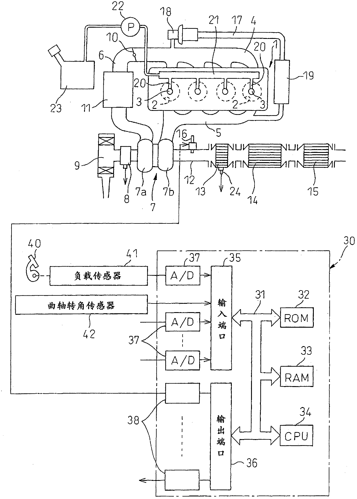
[0029] figure 1 An overall view of a compression ignition internal combustion engine is shown.

[0030] refer to figure 1 It can be seen that 1 denotes the main body of the internal combustion engine, 2 denotes the combustion chamber of each cylinder, 3 denotes an electronically controlled fuel injection valve for injecting fuel into each combustion chamber 2, 4 denotes an intake manifold, and 5 denotes an exhaust manifold. The intake manifold 4 is connected to an outlet of a compressor 7 a of an exhaust turbocharger 7 via an intake duct 6 , and an inlet of the compressor 7 a is connected to an air filter 9 via an intake air amount detector 8 . A throttle valve 10 driven by a stepping motor is disposed in the intake duct 6 , and a cooling device 11 for cooling intake air flowing through the intake duct 6 is disposed around the intake duct 6 . exist figure 1 In the illustrated embodiment, the engine cooling water is introduced into the cooling device 11 and the intake air is...


PUM


Abstract

A hydrocarbon supply valve (16), an oxidation catalyst (13), an exhaust gas purification catalyst (14), and an NOx selective reduction catalyst (15) are disposed in an engine exhaust gas passage in the aforementioned order from the upstream side. NOx is reduced in the exhaust gas purification catalyst (14) by lowering the air-fuel ratio of exhaust gas that flows into the exhaust gas purification catalyst (14) at predetermined intervals while maintaining a lean air-fuel ratio. NOx that is not reduced in the exhaust gas purification catalyst (14) is reduced by ammonia adsorbed in the NOx selective reduction catalyst (15). The air-fuel ratio of the exhaust gas that flows into the exhaust gas purification catalyst (14) is occasionally changed from lean to rich, at which time the ammonia generated in the exhaust gas purification catalyst (14) is adsorbed in the NOx selective reduction catalyst (15).

Description

technical field [0001] The present invention relates to an exhaust purification device for an internal combustion engine. Background technique [0002] There is known an internal combustion engine as follows: NO is arranged in the exhaust passage of the internal combustion engine X occlusion catalyst, the NO X The storage catalyst stores NO contained in the exhaust gas when the air-fuel ratio of the inflowing exhaust gas is lean. X , when the air-fuel ratio of the inflowing exhaust gas is a rich air-fuel ratio, the occluded NO is released X , in NO X In the exhaust passage of the internal combustion engine upstream of the occlusion catalyst, an oxidation catalyst with adsorption function is arranged. X NO release from occlusion catalyst X At this time, hydrocarbons are supplied to the exhaust passage of the internal combustion engine upstream of the oxidation catalyst, so that the inflow of NO X The air-fuel ratio of the exhaust gas storing the catalyst becomes rich (f...

Claims


Application Information

Patent Timeline
Patent Type & Authority Applications(China)
IPC IPC(8): F01N3/08B01D53/94F01N3/24
CPCB01D2255/202B01D53/9495F01N3/106B01D53/9422Y02T10/22B01D2251/208B01D53/9445F01N3/2033F01N2570/18F01N2560/06Y02T10/24B01D2255/102Y02T10/26F01N3/2066B01D53/9472F01N2560/026B01D53/944B01J23/40F01N3/0842F01N3/2073F01N3/36Y02T10/12B01D53/94F01N3/08F01N3/24
Inventor 美才治悠树吉田耕平井上三树男
Owner TOYOTA JIDOSHA KK
Why Eureka
Try Eureka