Tomograph
A technology of tomography and shooting position, which is used in measurement devices, computed tomography scanners, diagnosis, etc., can solve problems such as difficult alignment and time-consuming, and achieve good position accuracy, high-efficiency shooting, and easy repeatability. Effect
- Summary
- Abstract
- Description
- Claims
- Application Information
AI Technical Summary
Problems solved by technology
Method used
Image

Examples
Embodiment 1
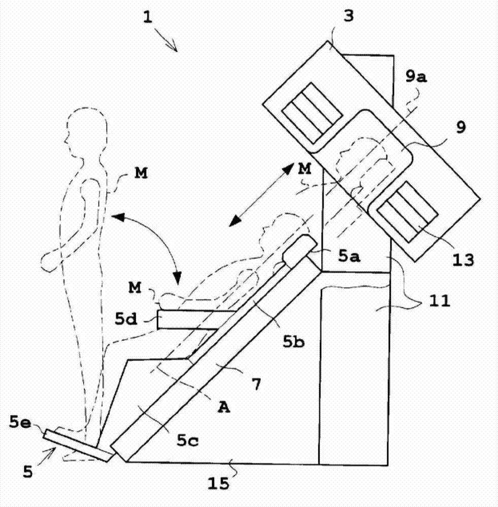
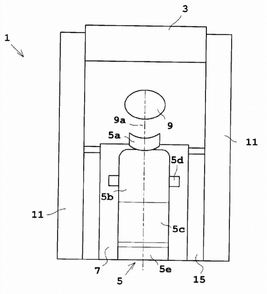
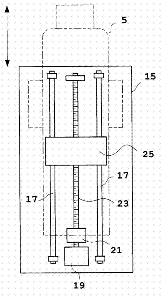
[0051] Hereinafter, Embodiment 1 of the present invention will be described with reference to the drawings. In addition, as the tomographic imaging apparatus of the present invention, a PET apparatus for the head will be described as an example. figure 1 It is a side view showing a schematic structure of the head PET device of Example 1 with a partial cutaway, figure 2 is its front view. in addition, image 3 is a diagram showing the chair movement mechanism, Figure 4 It is a block diagram showing the control system of the head PET apparatus.
[0052] refer to figure 1 as well as figure 2 . The head PET apparatus 1 of this embodiment includes a gantry 3 , a chair 5 on which the subject M sits, and a chair moving mechanism 7 for moving the chair 5 to an imaging position. In addition, the head PET apparatus 1 corresponds to the tomographic imaging device in the present invention, and the chair moving mechanism 7 corresponds to the imaging position moving mechanism in...
Embodiment 2
[0070] Next, Embodiment 2 of the present invention will be described. Figure 9 It is a side view showing a schematic structure of the head PET device of Example 2, partially cut away. Figure 10 From Figure 9 The symbol V indicates the structure of the gantry moving mechanism. In addition, the description of the structure overlapping with each of the above-mentioned embodiments is omitted.
[0071] refer to Figure 9 . On the basis of the structure of Embodiment 1, the head PET apparatus 1A of Embodiment 2 further has a scanning frame moving mechanism 41. The scanning frame moving mechanism 41 drives the scanning frame 3, and the subject M is connected to the scanning frame. The central axis 9a of the opening 9 of the gantry 3 is inserted into the opening 9 of the gantry 3 so as to be parallel. The gantry 3 is supported by a pair of support columns 11 via a gantry moving mechanism 41 . like Figure 10 As shown, the scanning frame moving mechanism 41 has a support tabl...
Embodiment 3
[0076] Next, Embodiment 3 of the present invention will be described. Figure 11 It is a side view showing a schematic structure of the head PET apparatus of Example 3 partially cut away. in addition, Figure 12 It is a figure which shows the structure of a chair angle change mechanism. In addition, the description of the structure overlapping with each of the above-mentioned embodiments is omitted.
[0077] refer to Figure 11 as well as Figure 12 . In addition to the above-described embodiments, the head PET apparatus 1B further includes a chair angle changing mechanism 57 for changing the angle between the backrest portion 5b and the seat portion 5c of the chair 5 . like Figure 12 As shown, the backrest portion 5b and the seat portion 5c of the chair 5 are connected so as to be rotatable around the support shaft 59 . Specifically, the support shaft 59 is fixed to the backrest part 5b, and the seat part 5c is connected to the backrest part 5b so as to be rotatable a...
PUM
 Abstract
Description
Claims
Application Information
 - R&D
- Intellectual Property
- Life Sciences
- Materials
- Tech Scout
- Unparalleled Data Quality
- Higher Quality Content
- 60% Fewer Hallucinations
Browse by: Latest US Patents, China's latest patents, Technical Efficacy Thesaurus, Application Domain, Technology Topic, Popular Technical Reports.
© 2025 PatSnap. All rights reserved.Legal|Privacy policy|Modern Slavery Act Transparency Statement|Sitemap|About US| Contact US: help@patsnap.com