
Cutting insert and cutting tool

A cutting insert and cutting tool technology, applied in the field of cutting tools and cutting inserts, can solve problems such as cutting edge damage, and achieve the effect of reducing cutting resistance and improving processing efficiency

Inactive Publication Date: 2012-11-14
TUNGALOY CORP
View PDF8 Cites 16 Cited by
  • Summary
  • Abstract
  • Description
  • Claims
  • Application Information

AI Technical Summary

Problems solved by technology

Therefore, in a cutting insert having a straight cutting edge, the cutting edge may be suddenly damaged at the moment of cutting into the workpiece.

Method used


Image

  • Cutting insert and cutting tool
  • Cutting insert and cutting tool
  • Cutting insert and cutting tool

Examples


Embodiment Construction

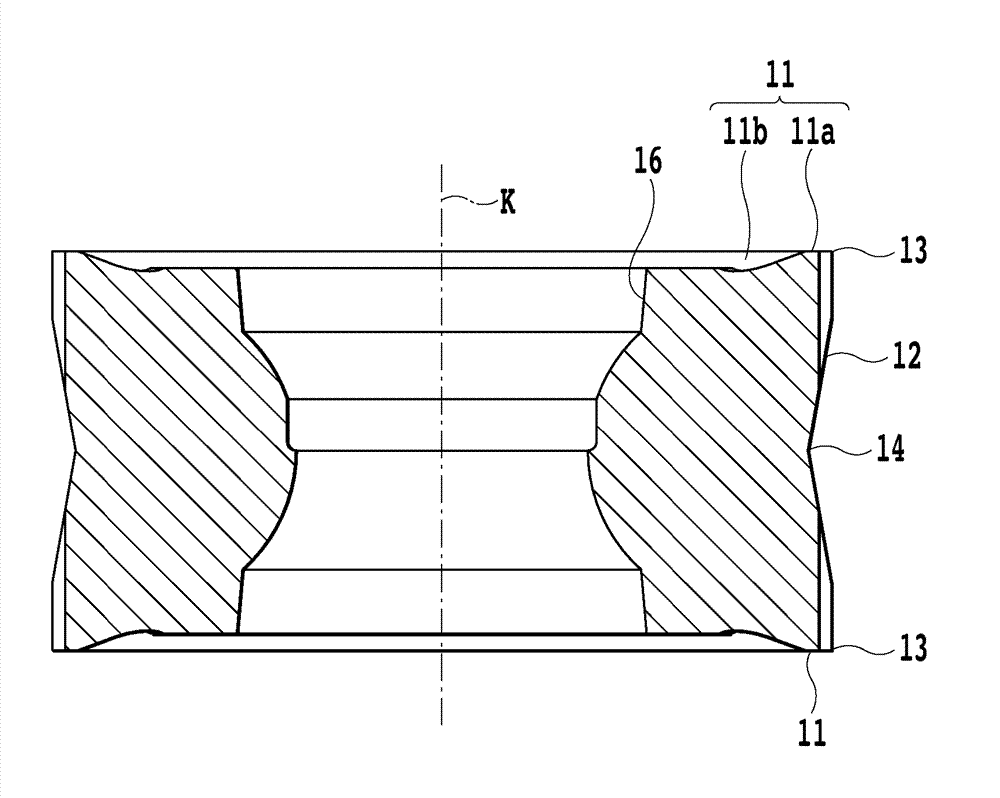
[0034] Refer to the following Figure 1 to Figure 8 One embodiment of the present invention will be described.

[0035] figure 1 as well as figure 2 The cutting tool 20 shown is a high feed cutter comprising a cutting tool body 21 and a plurality of cutting inserts 10 .

[0036] The cutting tool body 21 of the cutting tool 20 is as Figure 4 As shown in FIG. 21 , it has a substantially cylindrical shape, and a coupling hole 23 for coupling with a machine tool is provided in the center portion of the cutting tool body 21 to penetrate from the rear end to the tip. Furthermore, the cutting tool body 21 has a plurality of mounting seats 22 formed at equal intervals in the circumferential direction centering on the central axis J. As shown in FIG. The cutting insert 10 described later is attached to each of the plurality of mounts 22 . The cutting insert 10 is fixed to the cutting tool body 21 by bolts BT. In front of the mounting seat 22 formed at the tip of the cutting too...


PUM


Abstract

Provided is a cutting insert having a cutting edge that can inhibit the cutting resistance applied to a cutting boundary section from increasing with an increase in cutting depth. The cutting insert has one or more rake faces, a flank face, and a cutting edge formed at the intersection of the rake face and the flank face, and is removably attached to an attachment seat of a cutting tool body. The cutting edge has, in at least a portion thereof, a decreased-cutting-angle cutting edge section in which the cutting angle gradually decreases along the direction in which the cutting depth of the cutting edge increases. For example, the rake faces comprise an upper rake face formed on the upper face and a lower rake face formed on the lower face, the flank face is formed on the side face extending between the upper face and the lower face, and the cutting edge is formed at the intersection of the upper rake face and the flank face.

Description

technical field [0001] The present invention relates to a cutting insert and a cutting tool having the cutting insert. Background technique [0002] When cutting a workpiece, an optimal cutting tool is selected according to the type of processing, the material of the workpiece, and the like. Furthermore, one of the most important elements for selecting a cutting tool is the shape of the cutting edge of the cutting insert actually involved in cutting the workpiece. For example, when machining the concave shape of a mold, a cutting insert with a substantially arc-shaped cutting edge is used (see Patent Document 1), and when processing other molds, a cutting insert with a linear cutting edge is used (see Patent Document 1). Patent Document 2). [0003] Patent Document 1: Japanese Unexamined Patent Publication No. 2006-82168. [0004] Patent Document 2: Japanese Unexamined Patent Publication No. 2009-107051. [0005] The problem to be solved by the invention [0006] Howeve...

Claims


Application Information

Patent Timeline
Patent Type & Authority Applications(China)
IPC IPC(8): B23C5/20B23B27/00B23B27/14B23B51/00
CPCB23C2200/128B23C2200/208B23C2200/0455B23C5/2213B23C5/06B23C2200/0422B23C2200/205B23C2210/168Y10T407/2268Y10T407/235Y10T407/24B23C5/20B23B27/14B23B27/16
Inventor 吉冈史郎今田静惠
Owner TUNGALOY CORP
Learn More