
Laser damage testing device for optical thin film

A technology of laser damage and testing equipment, which is applied in the direction of measuring equipment, scientific instruments, weather resistance/light resistance/corrosion resistance, etc. It can solve the problems of difficulty in obtaining a wide range of light intensity parameter changes, uneven irradiation spots, etc., and achieve convenience The effect of optical path layout and parameter adjustment, improving measurement accuracy and reducing protection requirements

Inactive Publication Date: 2012-11-14
NORTHWEST INST OF NUCLEAR TECH
View PDF2 Cites 11 Cited by
  • Summary
  • Abstract
  • Description
  • Claims
  • Application Information

AI Technical Summary

Problems solved by technology

[0005] The present invention proposes an optical thin film laser damage testing device based on optical microscopic imaging and polarization attenuation. Uniformity, and it is difficult to obtain a wide range of light intensity parameter changes and other deficiencies

Method used


Image

  • Laser damage testing device for optical thin film
  • Laser damage testing device for optical thin film
  • Laser damage testing device for optical thin film

Examples


Embodiment Construction

[0027] Now in conjunction with embodiment, accompanying drawing, the present invention will be further described:

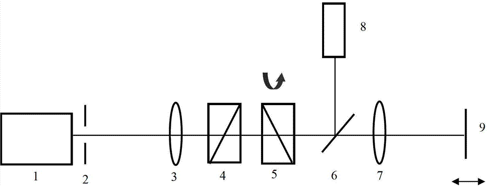
[0028] like figure 1 As shown, the optical thin film laser damage testing device of the present invention includes an optical power energy measuring instrument 8 and an aperture stop 2, a first lens 3, and an optical attenuator 4 / 5 arranged sequentially between the laser 1 and the coated lens 9 to be tested. , sampling beam splitter 6 and focusing lens 7; wherein aperture 2 is arranged on the front focal plane of the first lens 3, and the coating lens 9 to be measured is arranged on the back focal plane of focusing lens 7, selects the near aperture 2 place The object plane in the central uniform area of ​​the field beam is imaged to the coated mirror surface to be measured through the first lens 3 and the focusing lens 7 through the infinite distance microscopic imaging method, and the object plane and the coated mirror surface to be measured are respectively loc...


PUM

PropertyMeasurementUnit
lengthaaaaaaaaaa
lengthaaaaaaaaaa

Abstract

The invention discloses a laser damage testing device for an optical thin film. The laser damage testing device comprises an optical power energy measurement instrument, wherein an aperture, a first lens, an optical attenuator, a sampling beam splitter and a focusing lens are arranged between a laser device and a coated lens to be tested in sequence; the aperture is arranged on the front focal plane of the first lens, and the coated lens to be tested is arranged on the rear focal plane of the focusing lens; and the incident transmission light of the sampling beam splitter enters the focusing lens, and the reflection light enters the optical power energy measurement instrument. According to the laser damage testing device, the infinite microscopic imaging mode is adopted, the uniform radiation on an image plane is obtained, the wide-range adjustable optical attenuation is realized, the needed spot size can be easily obtained, and the test requirement of high-power excimer laser system on film damage is met.

Description

technical field [0001] The invention relates to an optical thin film testing device, in particular to an optical thin film laser damage testing device suitable for a high-power excimer laser system. Background technique [0002] Excimer laser systems are applied to a variety of optical thin films, and thin film laser damage measurement is of great significance to the reliability of the system. The laser damage test of optical thin films not only requires uniform irradiation, but also needs to change the laser power density incident on the thin film in a wide range to meet the requirements of various devices. changes for accurate and reliable measurements. [0003] "Intense Lasers and Particle Beams" (Vol.10, 1998, p123-126 and Vol.20, 2008, p509-512) disclosed a method for laser damage testing of optical thin films based on single lens focusing. Because of the love spot, it is difficult to obtain the desired uniform irradiation. [0004] In terms of beam attenuation and l...

Claims


Application Information

Patent Timeline
Patent Type & Authority Applications(China)
IPC IPC(8): G01N17/00
Inventor 赵学庆郑国鑫白婷薛全喜肖伟伟
Owner NORTHWEST INST OF NUCLEAR TECH
Learn More