Catalyst packing and catalytic oxidation defoaming device thereof
A defoaming device and catalytic oxidation technology, applied in the field of catalysis, can solve the problems of high cost of defoaming agents, pollutants, unsatisfactory effects, affecting the treatment effect and effluent quality, etc., and achieve the effect of small footprint
- Summary
- Abstract
- Description
- Claims
- Application Information
AI Technical Summary
Problems solved by technology
Method used
Image

Examples
Embodiment 1
[0024] The catalyst packing described in this embodiment is prepared by using coconut shell carbon with a diameter of 2-4mm as the base material, soaking in 5% copper sulfate solution for 20 hours, and then sintering and solidifying copper at 330°C.
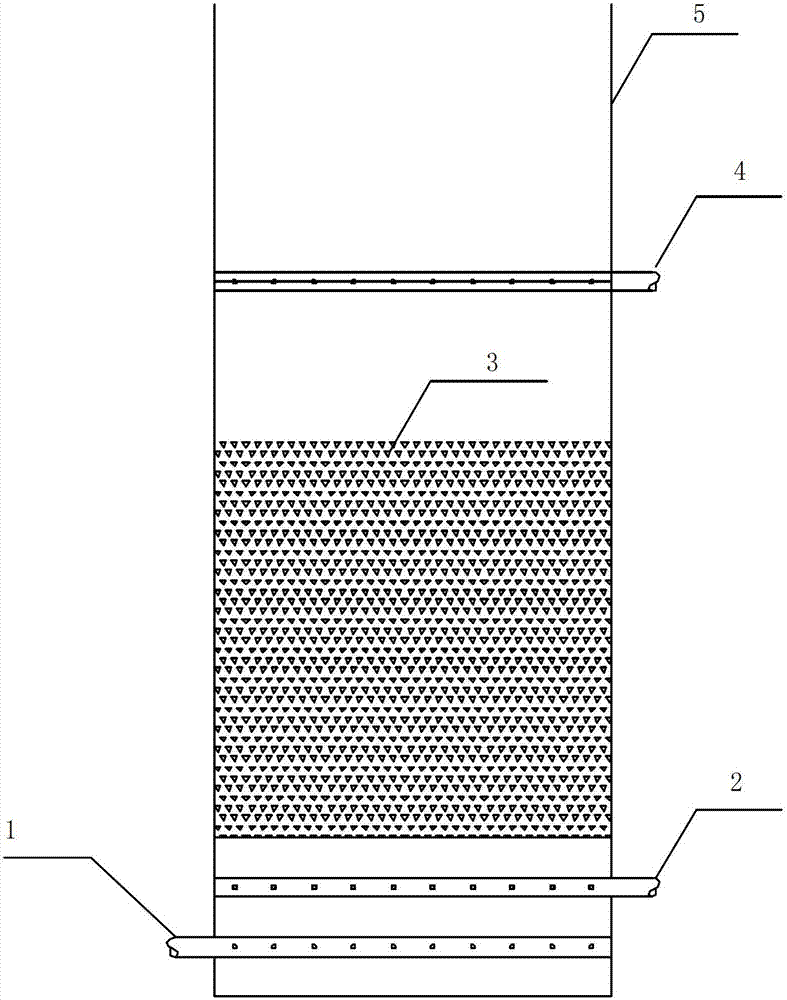
[0025] A catalytic oxidation defoaming device (such as figure 1 shown), including a tank body 5, a water inlet pipe 1, an air inlet pipe 2, a catalyst packing area 3, and a water outlet pipe 4, the water inlet pipe 1 is arranged at the bottom of the tank body 5, and the water outlet pipe 4 is arranged at the tank body 5 The top of the top, the catalyst packing area 3 is arranged between the water inlet pipe 1 and the water outlet pipe 4, the air inlet pipe 2 is arranged between the catalyst packing area 3 and the water inlet pipe 1, and the catalyst packing area is filled with the catalyst packing . The thickness of the catalyst packing area is 1.0m.
[0026] The cleaning wastewater produced by printing and dyeing, circuit boar...
Embodiment 2
[0029] The catalyst packing described in this embodiment is prepared by using coconut shell carbon with a diameter of 2-4mm as the base material, soaking in 3% copper sulfate solution for 28 hours, and then sintering and solidifying copper at 330°C.
[0030] A catalytic oxidation defoaming device (such as figure 1 shown), including a tank body, water inlet pipe, air inlet pipe, catalyst packing area, and water outlet pipe. The water inlet pipe is arranged at the bottom of the tank body, and the water outlet pipe is arranged at the top of the tank body. Between the water inlet pipe and the water outlet pipe, the inlet pipe is arranged between the catalyst packing area and the water inlet pipe, and the above catalyst packing is filled in the catalyst packing area. The thickness of the catalyst packing area is 1.5m.
[0031] The results of the application experiments are the same as those in the examples and are omitted.
Embodiment 3
[0033] The catalyst packing described in this embodiment is prepared by using coconut shell carbon with a diameter of 2-4mm as the base material, soaking in 8% copper sulfate solution for 20 hours, and then sintering and solidifying copper at 270°C.
[0034] A catalytic oxidation defoaming device (such as figure 1 shown), including a tank body, water inlet pipe, air inlet pipe, catalyst packing area, and water outlet pipe. The water inlet pipe is arranged at the bottom of the tank body, and the water outlet pipe is arranged at the top of the tank body. Between the water inlet pipe and the water outlet pipe, the inlet pipe is arranged between the catalyst packing area and the water inlet pipe, and the above catalyst packing is filled in the catalyst packing area. The thickness of the catalyst packing area is 1.0m.
[0035] Application experiment result is identical with embodiment 1, omits.
PUM
| Property | Measurement | Unit |
|---|---|---|
| diameter | aaaaa | aaaaa |
| thickness | aaaaa | aaaaa |
| thickness | aaaaa | aaaaa |
Abstract
Description
Claims
Application Information
 - R&D
- Intellectual Property
- Life Sciences
- Materials
- Tech Scout
- Unparalleled Data Quality
- Higher Quality Content
- 60% Fewer Hallucinations
Browse by: Latest US Patents, China's latest patents, Technical Efficacy Thesaurus, Application Domain, Technology Topic, Popular Technical Reports.
© 2025 PatSnap. All rights reserved.Legal|Privacy policy|Modern Slavery Act Transparency Statement|Sitemap|About US| Contact US: help@patsnap.com