Automatic clamping mechanism in steel bar bender

An automatic clamping and steel bending technology, applied in the field of steel bending machines, can solve the problems of low processing efficiency, inconvenient processing, labor-intensive and labor-intensive, etc., and achieve the effects of high processing efficiency, simple structure and high degree of automation

Active Publication Date: 2012-11-14
TJK MACHINERY TIANJIN
View PDF6 Cites 3 Cited by
  • Summary
  • Abstract
  • Description
  • Claims
  • Application Information

AI Technical Summary

Problems solved by technology

Inconvenient processing, laborious and laborious, and low processing efficiency

Method used


Image

  • Automatic clamping mechanism in steel bar bender
  • Automatic clamping mechanism in steel bar bender
  • Automatic clamping mechanism in steel bar bender

Examples


Embodiment Construction

[0016] Embodiments of the present invention will be further described below in conjunction with the accompanying drawings.

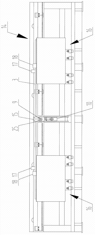
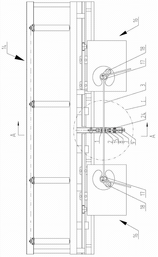
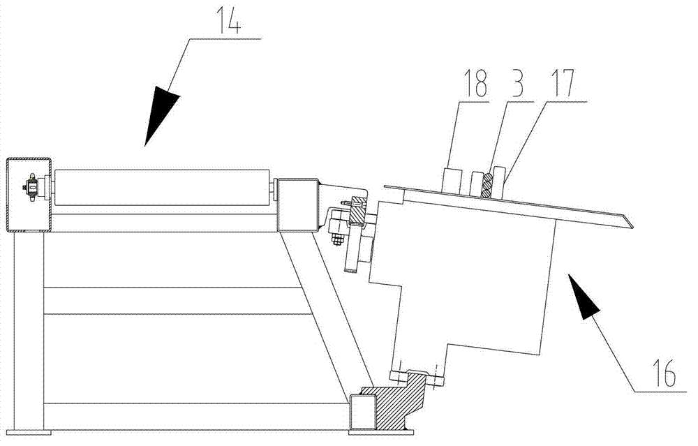
[0017] As shown in the figure, the present invention provides an automatic clamping mechanism in a steel bar bending machine, the automatic clamping mechanism includes a bending frame 14, and the automatic clamping mechanism is arranged on the bending frame on one side of the steel bar bending main machine 16 14, the structure of the automatic clamping mechanism includes: a circular track 7 arranged vertically to the axis of the steel bar 3 is supported on the bending frame 14; a two-way piston rod cylinder 10 is fixed on the circular track 7, so The two-way piston rod movement axis in the two-way piston rod cylinder 10 is parallel to the axis of the circular track 7; on the two-way piston rod of the two-way piston rod cylinder 10, one end of a pair of clamping arms 15 with the same mirror image structure is respectively fixed , the through holes of the ...


PUM


Abstract

The invention discloses an automatic clamping mechanism in a steel bar bender. The automatic clamping mechanism comprises a bending rack, wherein a circular track is supported on the bending rack; a bidirectional piston rod cylinder is fixed on the circular track; a bidirectional piston rod moving axis inside the bidirectional piston rod cylinder is parallel to the axis of the circular track; one ends of a pair of clamping arms of which the mirror symmetry structures are the same are fixed on the bidirectional piston rod of the bidirectional piston rod cylinder respectively; through holes of the pair of clamping arms are respectively in sliding match on the circular track; the other ends of the pair of clamping arms are respectively provided with clamping plates; the bidirectional piston rod cylinder drives the pair of clamping arms to slide along the circular track so as to make the clamping plates tightly clamp a reinforcing steel bar from two sides. The clamping mechanism has the beneficial effects that with the adoption of the automatic clamping mechanism of the steel bar bender, the reinforcing steel bar can be automatically clamped while being bent; the convenience is provided for operating personnel of the reinforcing steel bar machining equipment; and the clamping mechanism has the advantages of high automation degree, simple structure, stable working, time conservation and labor conservation and high working efficiency.

Description

technical field [0001] The invention relates to a steel bar bending machine, in particular to an automatic clamping mechanism in the steel bar bending machine. Background technique [0002] In the existing steel bar bending machines, some need to manually take the steel bar to the equipment to complete the processing. In order to make it convenient for the operator to take the steel bar, the steel bar processing equipment is usually set near the steel bar conveying roller table. When the steel bar passes through the conveying roller table After being transported to the designated position of the steel bar processing equipment, the transport is stopped, and the steel bar is manually placed on the bending machine, and the two bending main machines move back and forth on the slide to adjust the distance between the two bending main machines to bend steel bars of different lengths. When bending the steel bar, the steel bar is easy to slide left and right to make the curved steel...

Claims


Application Information

Patent Timeline
IPC IPC(8): B21F1/00
Inventor 陈振东
Owner TJK MACHINERY TIANJIN
Why Eureka
Try Eureka