
System for automatically testing service life of probe

An automatic test system and probe technology, applied in measuring devices, measuring electrical variables, instruments, etc., can solve problems such as probe failure, and achieve the effect of accurate test data

Active Publication Date: 2014-07-02
CENT SOUTH UNIV
View PDF5 Cites 0 Cited by
  • Summary
  • Abstract
  • Description
  • Claims
  • Application Information

AI Technical Summary

Problems solved by technology

[0003] However, the microprobe is in contact with the IC during the test process, and the contact pressure is related to the measured electrical signal value. The test probes of a large number of IC products contact the needle, the internal spring of the probe, the wear of the needle and the needle tube, etc. Causes the probe to fail, so the manufactured microprobe needs to be evaluated for its performance and lifetime

Method used


Image

  • System for automatically testing service life of probe

Examples


Embodiment Construction

[0015] The present invention will be further described in detail below in conjunction with the accompanying drawings and specific embodiments.

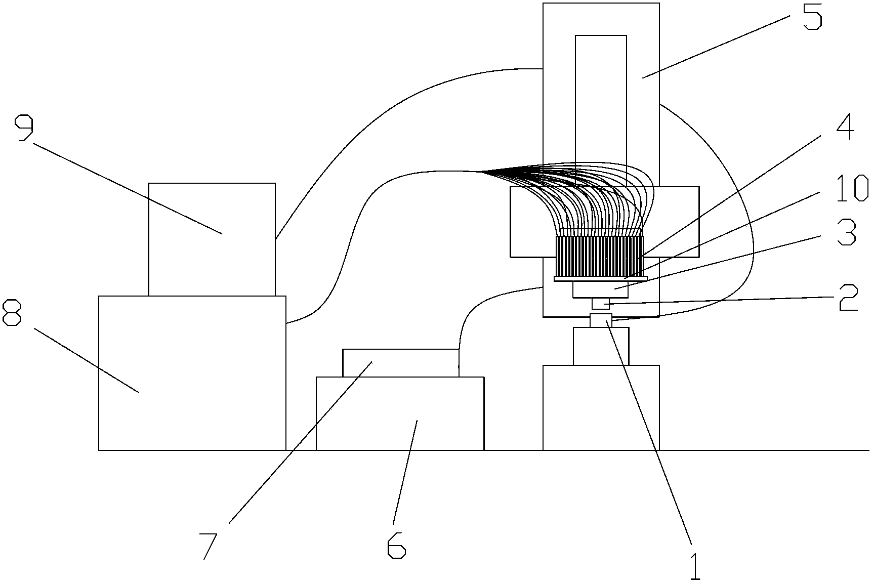
[0016] Such as figure 1 Shown: An automatic test system for probe life, such as figure 1 As shown, the high-frequency response force sensor 1 is placed on the platform, and the single probe or multiple probes 2 to be tested are loaded into the probe holder 3. According to the size of the probe 2, its diameter is generally 50-300 Micron, the probe holder 3 that fixes the probe 2 can fix one or more probes 2 in a probe holder 3 at the same time to meet the simultaneous measurement requirements of a single probe and multiple probes. The circuit board 10 on the fixture 3 leads the electrode of the probe 2 out, and then connects with the four-wire tester 8 through the probe electrode lead-out line 4 connected to the circuit board 10, and collects the contact of the probe 2 through the four-wire tester 8. The change of resistance, the pro...


PUM


Abstract

The invention discloses a system for automatically testing the service life of a probe. The system comprises a touching force sensor, the probe, a probe clamp, a probe electrode outgoing line, an up-down moving device, a four-wire type tester and a data processing system, wherein the data processing system is used for automatically saving tested data and analyzing the data in real time. The system is characterized in that the probe clamp is mounted on the moving end of the up-down moving device; the probe is mounted below the probe clamp; a circuit board for leading out the electrode of the probe is mounted above the probe clamp and is connected with the input end of the four-wire type tester by the probe electrode outgoing line; the touching force sensor is fixed under the probe and is connected with the data processing system by a wire; and the output end of the four-wire type tester is connected with the data processing system. The system for automatically testing the service life of the probe is simple in structure and precise in tested data, and can implement the automatic evaluation for the service life of the probe.

Description

technical field [0001] The invention relates to an automatic test system for probe life. Background technique [0002] After each integrated circuit (IC) is packaged, the performance of the product needs to be tested. IC testing is juxtaposed with IC design, IC manufacturing and IC packaging, forming the four pillars of the IC industry. The characteristic of the cost development of the semiconductor industry is that its unit function manufacturing cost decreases by an average of 25% to 30% per year, while the test cost increases by an average of 10.5% per year. Use a microprobe (needle diameter 50-500 microns) to contact the bump of the IC chip, input voltage / current signals to the chip, and obtain the electrical signal of the IC chip from the microprobe, so as to analyze whether the electrical performance of the IC chip meets the requirements IC product requirements, this micro-probe test method has become one of the important ways to test the electrical performance of IC ...

Claims


Application Information

Patent Timeline
Patent Type & Authority Patents(China)
IPC IPC(8): G01R35/02
Inventor 李军辉刘灵刚邓路华张小龙韩雷王福亮
Owner CENT SOUTH UNIV
Learn More