Mounting and clamping dual-purpose knife set for facing head machining

A technology of flat rotating disc and knife sleeve, which is applied in metal processing equipment, metal processing mechanical parts, clamping and other directions, can solve the problems of difficult machining of the inner cavity of the steam turbine, the incompatibility of the knife sleeve, and the poor adaptability, etc. Low cost, simple structure and good applicability

Active Publication Date: 2014-06-18
HARBIN TURBINE +1
View PDF5 Cites 0 Cited by
  • Summary
  • Abstract
  • Description
  • Claims
  • Application Information

AI Technical Summary

Problems solved by technology

[0003] The purpose of the present invention is to solve the problems that existing tool sets used for processing inner cavities of steam turbines have the problem that the tool sets cannot be used universally, the adaptability is poor, and it is difficult to process the inner cavities of steam turbines, and further provide a tool for flat rotating discs. Processing and clamping dual-purpose tool sets

Method used


Image

  • Mounting and clamping dual-purpose knife set for facing head machining
  • Mounting and clamping dual-purpose knife set for facing head machining
  • Mounting and clamping dual-purpose knife set for facing head machining

Examples


specific Embodiment approach 1

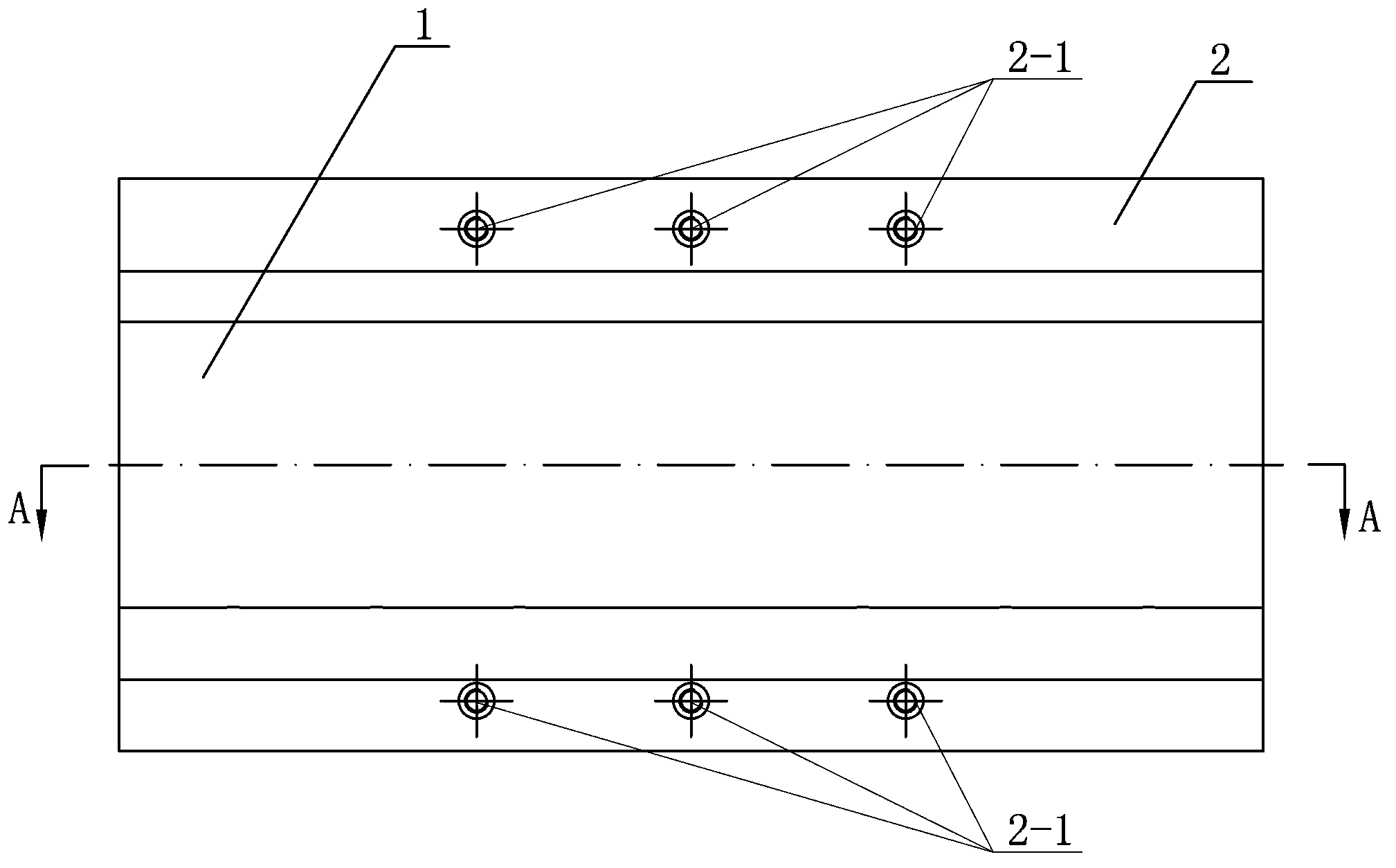
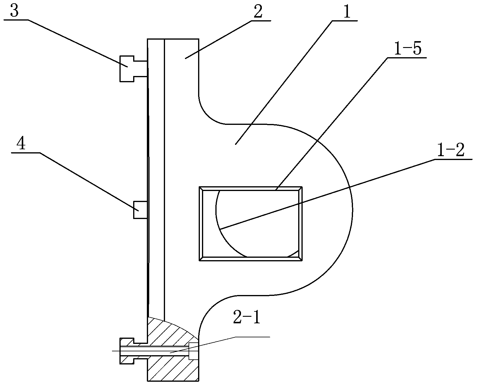
[0008] Specific implementation mode 1: Combination Figure 1-Figure 5 Explain that a clamping dual-purpose tool holder for flat-rotating disk processing in this embodiment includes a cylinder 1, an octahedron 2, two connecting bodies 3, and two shank keys 4;

[0009] The cross-sectional shape of the shank key 4 is a waist shape, the longitudinal section of the connecting body 3 is a T-shape, the octahedron 2 is a longitudinal cross-sectional shape of an octahedron with a rectangular upper end and an isosceles trapezoid at the lower end, etc. The long base side of the waist trapezoid is coplanar with the long side of the rectangle. The cylinder 1 has round holes 1-2 along its axial direction from one end face to the radial center line MN. The round holes 1-2 are used for installation. Tool holder, the cylinder 1 is machined with rectangular holes 1-5 along its axial direction from the other end surface to the radial center line MN. The rectangular holes 1-5 are used to install the...

specific Embodiment approach 2

[0010] Specific implementation manner two: combination Figure 4 To illustrate this embodiment, the knife sleeve of this embodiment also includes four first screws 5, each shank key 4 is provided with two first through holes 4-1, and the upper end surface of the octahedron 2 is connected to each A first threaded hole 2-2 is provided at a position corresponding to a through hole 4-1, and each shank key 4 and the octahedron 2 are provided in the first through hole 4-1 and connected with the first threaded hole 2-2. The threaded first screw 5 can be detachably connected. With this setting, the connection is efficient and reliable, meeting actual needs and design requirements.

specific Embodiment approach 3

[0011] Specific implementation mode three: combination figure 1 , figure 2 with Figure 5 To describe this embodiment, each connecting body 3 and the octahedron 2 described in this embodiment are coaxially provided with a second threaded hole 2-1. This arrangement facilitates the insertion of screws, which are tightened into the grooves of the machine tool pan through the screws, and facilitates the secure connection between the tool sleeve of the present invention and the machine tool pan. Others are the same as the first or second embodiment.


PUM


Abstract

The invention provides a mounting and clamping dual-purpose knife set for facing head machining, especially for the machining of a facing head of an inner die cavity of an assembly of a steam turbine, in order to solve the problems of the existing knife set for machining the inner cavity of the assembly of the steam turbine, such as failure in universality, poor adaptability and difficulty in machining of the inner die cavity of the assembly of the steam turbine. The mounting and clamping dual-purpose knife set provided by the invention comprises a cylinder, an octahedron, two connecting bodies and two handle keys, the cylinder is provided with a round hole in the axial direction on one side from one end face to a center line, the cylinder is provided with a rectangular hole in the axial direction on one side from the other end face to the midperpendicular, the cylinder and the octahedron are integrated into a whole, the two connecting bodies are arranged on the lower end face of the octahedron in parallel, the octahedron and the two connecting bodies are integrated into a whole, the lower end face of the octahedron between the two connecting bodies is provided with two handle keys in parallel in the axial direction of the cylinder, and the two handle keys are connected with the octahedron. The mounting and clamping dual-purpose knife set is used for facing head machining.

Description

Technical field [0001] The invention relates to a clamping dual-purpose tool sleeve used for processing the inner cavity of a part sleeve of a steam turbine. Background technique [0002] The shape and structure of the part sleeve of the steam turbine are complicated, and some processes require turning. However, due to the shape and structure of the workpiece, it cannot be processed on a lathe. The only option is to use a flat-rotating disk attachment on a boring and milling machine. The flat-rotating disk processing is better than a lathe Machining has its advantages. The lathe uses the workpiece to rotate and the tool performs linear movement to complete the machining. The cutting speed cannot be very large and there are limitations. In the case of boring and milling machines, the workpiece does not move. The tool moves linearly while rotating at high speed to complete the turning processing of the profile. The high-speed rotation of the tool for flat-rotation processing is hig...

Claims


Application Information

Patent Timeline
Patent Type & Authority Patents(China)
IPC IPC(8): B23Q3/00
Inventor 马桂君车延超高岩刘滨刚袁明于洪亮李久雷张大伟孟阳任建奎安志伟
Owner HARBIN TURBINE
Why Eureka
Try Eureka