Clamp tool table capable of rotating and displacing

A technology of tooling tables and fixtures, applied in positioning devices, clamping, manufacturing tools, etc., can solve the problems of inconvenient production process, inconvenient fastening and positioning of tooling tables, and inability to provide movable actions, so as to reduce operation and processing Difficulty, the effect of facilitating the fastening and positioning of the workpiece

Inactive Publication Date: 2016-12-07
江门市弘程精密制造有限公司
View PDF6 Cites 14 Cited by
  • Summary
  • Abstract
  • Description
  • Claims
  • Application Information

AI Technical Summary

Problems solved by technology

[0002] In production and processing, some large-scale combined workpieces need to be positioned and assembled and other processing procedures at the same time. While satisfying the fixed positioning, certain activities must be provided. However, the fastening and positioning of the traditional tooling table is not convenient, and it is also It cannot provide enough activities to match the processing procedure, which is inconvenient in the production process

Method used


Image

  • Clamp tool table capable of rotating and displacing
  • Clamp tool table capable of rotating and displacing

Examples


Embodiment Construction

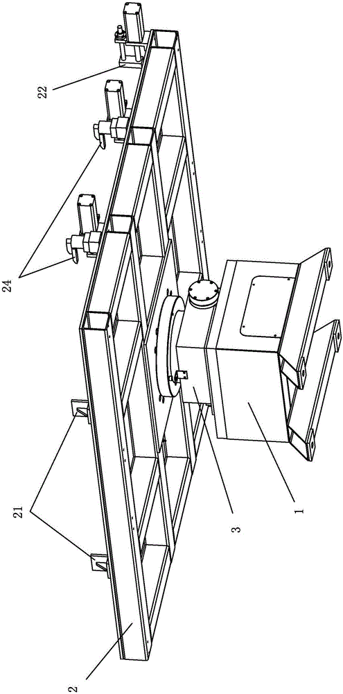
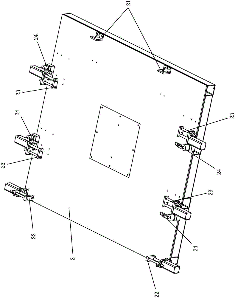
[0016] refer to figure 1 and figure 2 , a rotatable and displaceable fixture tooling platform of the present invention includes a base 1 and a machine platform 2, the machine platform 2 is mounted on the base 1 through a rotating seat 4, the main body of the rotating seat 3 and the base 1. Tightly connected, the rotating disk of the rotating seat 3 is connected with the bottom surface of the machine table 2. The rotating seat 3 is provided with a driving motor to drive its rotating disk through a transmission mechanism. The edges of the machine table 2 are respectively provided with positioning stops that limit the movement of the workpiece to achieve positioning. Plate 21, clamping movable baffle 22, top connecting movable baffle 23 and pressure plate 24, the positioning baffle 21 and clamping movable baffle 22 are respectively located on the lateral edges of the machine 2, and the top connecting movable The baffle plate 23 and the pressing plate 24 are respectively arrange...


PUM


Abstract

The invention discloses a clamp tool table capable of rotating and displacing. The clamp tool table capable of rotating and displacing comprises a base and a machine table; the machine table is mounted on the base through a rotating seat; the main body of the rotating seat is in fastening connection with the base; a rotating disc of the rotating seat is connected with the bottom surface of the machine table; the rotating seat is provided with a driving motor which drives the rotating disc of the rotating seat through a transmission mechanism; positioning baffles, clamping movable baffles, butting movable baffles and pressing plates which limit the movement of a workpiece to realize positioning are respectively arranged at the edges of the machine table; the positioning baffles and the clamping movable baffles are oppositely and respectively positioned on the edges of the two sides in the transverse direction of the machine table; the butting movable baffles and the pressing plates are respectively and uniformly arranged on the edges of the two sides of the longitudinal direction of the machine table. According to the clamp tool table, the workpiece can be rotated and displaced; moreover, the workpiece is convenient to fasten and position; the operating and machining difficulties in a production process are greatly reduced.

Description

technical field [0001] The invention relates to a rotatable and displaceable fixture tooling table. Background technique [0002] In production and processing, some large-scale combined workpieces need to be positioned and assembled and other processing procedures at the same time. While satisfying the fixed positioning, certain activities must be provided. However, the fastening and positioning of the traditional tooling table is not convenient, and it is also It cannot provide enough activities to cooperate with the processing procedure, which is inconvenient in the production process. Contents of the invention [0003] In order to overcome the deficiencies of the prior art, the present invention provides a rotatable and displaceable clamp tooling table, which can improve the inconvenience of the workbench. [0004] The technical solution adopted by the present invention to solve its technical problems is: [0005] A rotatable and displaceable jig tooling table include...

Claims


Application Information

Patent Timeline
Patent Type & Authority Applications(China)
IPC IPC(8): B23Q3/06B23Q1/26
CPCB23Q3/06B23Q1/262
Inventor 李英志吴健辉
Owner 江门市弘程精密制造有限公司
Why Eureka
Try Eureka