
LED lamp detecting device

A technology of LED lamps and detection devices, applied in the field of machinery, can solve the problems of narrow application range, inability to detect the photoelectric parameters and working state parameters of LED components, etc., and achieve the effects of wide testing range, reducing the use of facilities, and saving costs.

Inactive Publication Date: 2012-10-24
台州市远东铁马自动化设备有限公司
View PDF6 Cites 31 Cited by
  • Summary
  • Abstract
  • Description
  • Claims
  • Application Information

AI Technical Summary

Problems solved by technology

This device mainly transmits the LED components, and the detection device is used as a secondary structure. Its scope of application is narrow, and it can only meet the requirements of the automatic placement machine, and the device cannot detect the photoelectric parameters and working state parameters of the LED components.

Method used


Image

  • LED lamp detecting device
  • LED lamp detecting device
  • LED lamp detecting device

Examples


Embodiment Construction

[0030] The following are specific embodiments of the present invention and in conjunction with the accompanying drawings, the technical solutions of the present invention are further described, but the present invention is not limited to these embodiments.

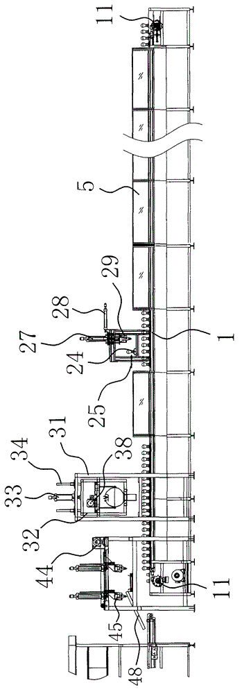
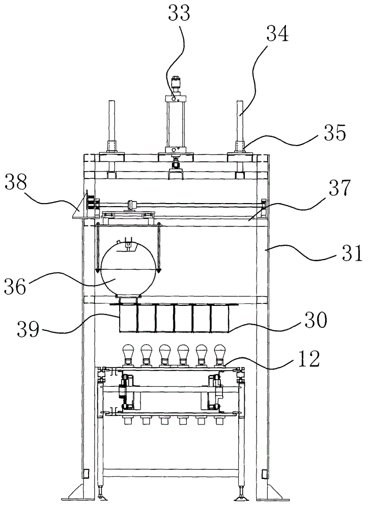
[0031] Such as figure 1 The detection device for the LED lamp shown includes a strip-shaped workbench 1 arranged horizontally, a transmission belt arranged on the workbench 1 and along the length direction of the workbench 1, and a motor-driven motor driven by a motor at the bottom of the workbench 1. The sprocket 11 that is used to drive the transmission of the transmission belt. Such as figure 1 As shown, the two ends of the transmission belt intersect so that the entire transmission belt looks elliptical. In this embodiment, there are two sets of corresponding sprockets 11, and each set of sprockets 11 is respectively located at the two ends of the elliptical transmission belt. Such as Figure 1-4 As shown, the surfa...


PUM


Abstract

The invention provides an LED lamp detecting device, and belongs to the technical field of detection. The LED lamp detecting device solves problems of small detection range and low precision of an existing LED lamp detecting device. The LED lamp detecting device comprises an elongated worktable, a conveying belt and chain wheels, the elongated worktable is disposed horizontally, the conveying belt is arranged on the worktable, the chain wheels used for driving the conveying belt to transmit LED lamps are disposed on the lower portion of the worktable and driven by a motor, the conveying belt is elliptical, the chain wheels are respectively positioned at two ends of the elliptical conveying belt, a plurality of lamp bank holders which are arranged along the width direction of the worktable are disposed on the surface of the conveying belt and are uniformly distributed, each lamp bank holder consists of 6-10 lamp holders uniformly distributed, and a high-voltage detecting unit, a photoelectric parameter testing unit and an automatic separating unit are respectively arranged above the worktable and are sequentially distributed along the conveying direction of the conveying belt. The LED lamp detecting device has the advantages of wide detection range, high detection precision and the like.

Description

technical field [0001] The invention belongs to the technical field of machinery, and relates to a detection device, in particular to a detection device for an LED lamp. Background technique [0002] LED (Light Emitting Diode) is the English abbreviation of Light Emitting Diode, which is a solid-state semiconductor device that can directly convert electrical energy into light. With the improvement of people's living standards, the development of urban lighting projects and highway networks, the requirements for indoor lighting, road lighting and flood lighting of buildings are increasing, so the demand for various LED lighting sources and LED lamps It is getting bigger and bigger, and the requirements are constantly improving. At the same time, it also promotes the rapid development of the LED lighting industry, and various new types of high-efficiency and energy-saving LED lamps are also emerging. The key to evaluating the quality of any LED lamp is to see what kind of lig...

Claims


Application Information

Patent Timeline
IPC IPC(8): G01R31/26G01M11/02G01R31/44
Inventor 张臻陈明秋
Owner 台州市远东铁马自动化设备有限公司
Learn More