LED (Light-Emitting Diode) light source based on special module

A technology of LED light source and LED chip, applied in the field of LED lighting, can solve the problems of large light loss, complex process, messy lamps, etc., to achieve the effect of heat dispersion, simplified process, soft and uniform optical effect

Inactive Publication Date: 2012-10-24
HENAN XINTE PHOTOELECTRIC TECH
View PDF15 Cites 0 Cited by
  • Summary
  • Abstract
  • Description
  • Claims
  • Application Information

AI Technical Summary

Problems solved by technology

[0004] The technical problem to be solved by the present invention is to provide an LED light source based on a special-shaped module, which solves the technical problems of existing LED lighting such as large loss of light, high cost, glare, complicated process, difficult heat dissipation, and messy lamps.

Method used


Image

  • LED (Light-Emitting Diode) light source based on special module
  • LED (Light-Emitting Diode) light source based on special module
  • LED (Light-Emitting Diode) light source based on special module

Examples


Embodiment 1

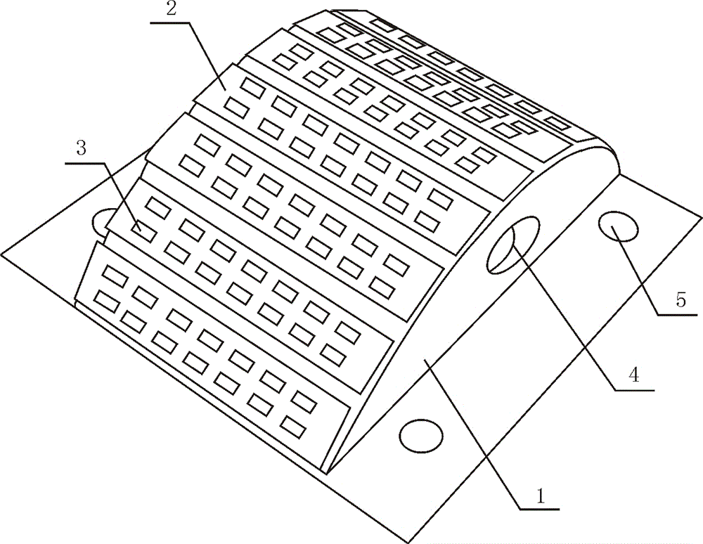
[0018] Such as figure 1 As shown, a LED light source based on a special-shaped module includes a solid metal module 1, the upper surface of the module 1 is a non-planar structure, and the upper surface of the module 1 is a cylindrical surface, a spherical surface, a polygonal cylinder surface or paraboloid. In this embodiment, the module 1 is semi-cylindrical, and its upper surface is a cylindrical surface. The module 1 is covered with a high thermal conductivity substrate 2 corresponding to its shape. The substrates 2 are rectangular, and two pairs are closely pasted on the upper surface of the module 1, so that the upper surface of the substrate 2 is also a non-planar structure. Alternatively, the base plate 2 covers the entire upper part of the module 1 as a whole. The substrate 2 includes a bottom layer of low thermal resistance, an insulating and heat-conducting layer, and an electrolytic copper foil layer laid sequentially from bottom to top. The electrolytic copper fo...

Embodiment 2

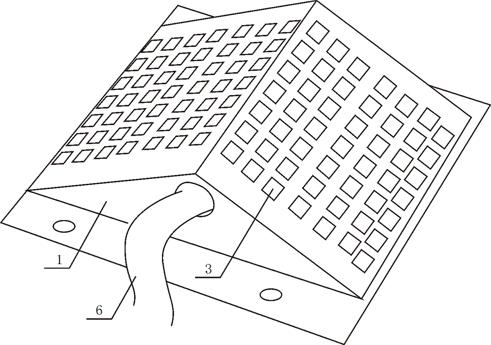
[0021] Such as figure 2 As shown, an LED light source based on a special-shaped module is different from Embodiment 1 in that the module 1 is a horizontal triangular prism. There are two substrates 2, both of which are rectangular, and are pasted on the upper surface of the module 1; or the substrate 2 covers the entire upper surface of the module 1 as a whole. The through hole 4 runs through the entire triangular prism, and a heat pipe 6 is arranged in the through hole 4 to quickly transfer the heat on the module 1 to the outside air through the heat pipe 6 .

Embodiment 3

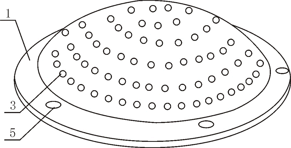
[0023] Such as image 3 As shown, an LED light source based on a special-shaped module is different from the first embodiment in that the upper surface of the module 1 is spherical. The bottom of the module 1 extends around to form a circle of edges, and the edges are provided with fixing holes 5 . The entire substrate 2 is attached to the upper surface of the module 1 .

[0024] This LED light source can be widely used in high-power street lamps and flood lamp series.

[0025] In short, there are two directions for the realization of LED high-power module light sources: one is to improve the substrate manufacturing process and make special-shaped substrates, and the investment in equipment improvement is small; the other is to improve the operation track of packaging machinery, which requires a large investment, but in terms of structure and performance , will be much better. Therefore, an ideal high-power LED light source is preferably formed by directly packaging a point...


PUM


Abstract

The invention discloses an LED (Light-Emitting Diode) light source based on a special module, relates to the technical field of LED illumination, and in particular relates to comprehensive optimization in the aspects of light emitting angle, illuminance area, optical configuration and illuminance, heat-sinking treatment and service life and the like. The LED light source comprises a solid-core metal module, wherein the upper surface of the module is of a non-planar structure; the module is covered by a high-heat-conducting substrate corresponding to the shape of the module; the substrate comprises a low-heat-resistance underlayer, an insulating heat-conducting layer and an electrolytic copper-foil layer which are laid from bottom to top in sequence; a plurality of LED chip fixing points are distributed on the electrolytic copper-foil layer; and LED chips are distributed on the substrate by the LED chip fixing points and are externally packaged by protective glue. The LED light source has the advantages that the structure is simple, the application is convenient, the whole light emitting angle is large, the light loss is less, double radiation is achieved, the service life is long and the optical radiation can be reduced.

Description

technical field [0001] The invention relates to the technical field of LED lighting, in particular to a high-power LED light source based on a special-shaped module. Background technique [0002] At present, high-power LED lighting, whether it is an integrated light source or a variety of substrate chip light sources, is a planar light source. When LED lighting needs to achieve a certain illuminance and illumination area, it is necessary to install optical devices such as lenses. However, these optical devices will decelerate the light source and light beam, resulting in a certain amount of light loss. Especially for integrated light sources, since each PN junction light beam has a certain angle, the distance between the PN junctions of integrated light sources is small, and the beams interfere with each other to cause light loss. In addition, the astigmatism lens installed in the application of each integrated light source, Light loss is also generated. It is conceivable ...

Claims


Application Information

Patent Timeline
Patent Type & Authority Applications(China)
IPC IPC(8): F21S2/00F21V19/00F21V29/00F21Y101/02F21V29/71F21V29/83
Inventor 张盛辉
Owner HENAN XINTE PHOTOELECTRIC TECH
Why Eureka
Try Eureka