Filter loading broadband three-gap coupling output cavity structure

A technology of coupling output and output cavity, applied in the microwave field, can solve the problems of lengthening the interaction distance, increasing the weight of the focusing system, and the application of unfavorable interaction klystrons.

Inactive Publication Date: 2012-10-17
INST OF ELECTRONICS CHINESE ACAD OF SCI
View PDF2 Cites 5 Cited by
  • Summary
  • Abstract
  • Description
  • Claims
  • Application Information

AI Technical Summary

Problems solved by technology

The advantage is that the processing, welding and assembly are simple. The disadvantage is that compared with the traditional reentrant coupling cavity structure, the interaction distance will be longer, which will increase the weight of the focusing system, which is not conducive to expanding the application of the interaction klystron in space.

Method used


Image

  • Filter loading broadband three-gap coupling output cavity structure
  • Filter loading broadband three-gap coupling output cavity structure
  • Filter loading broadband three-gap coupling output cavity structure

Examples


Embodiment Construction

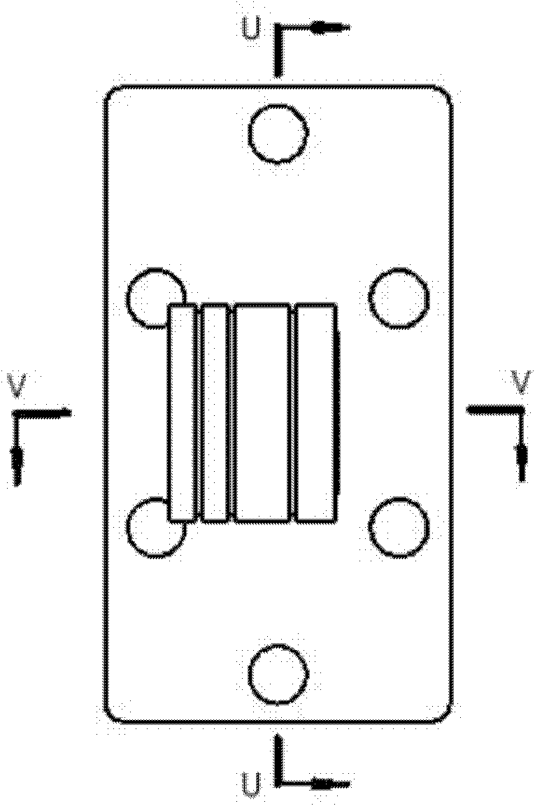
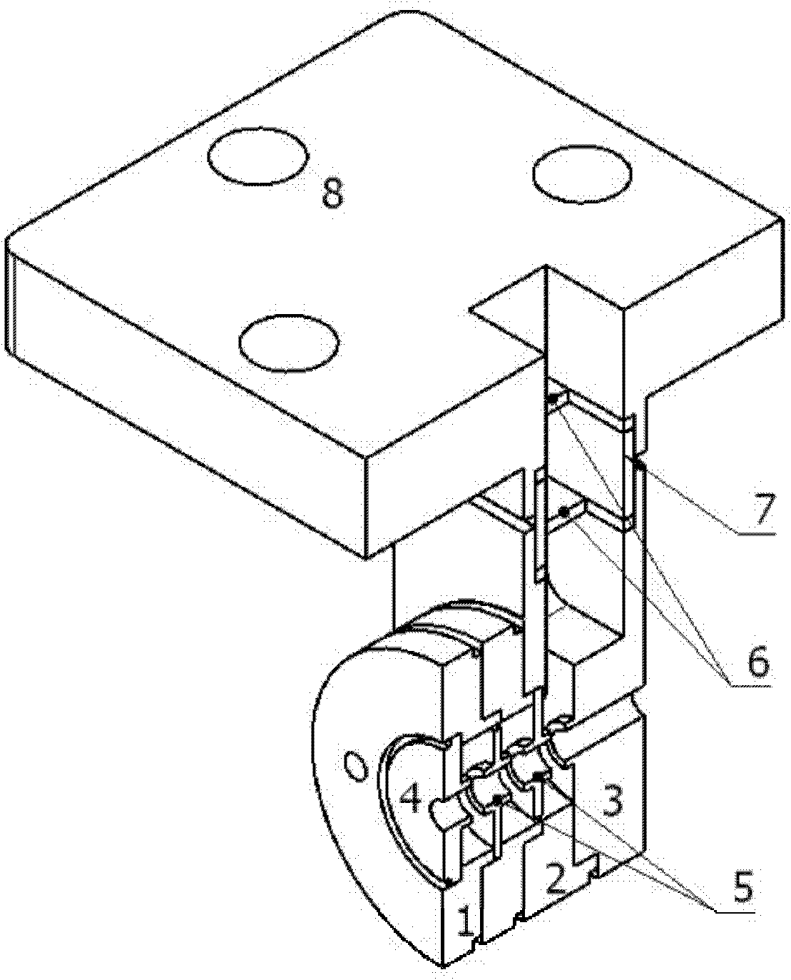
[0032] In order to help a better understanding of the present invention, specific embodiments of the present invention will be described below with reference to the accompanying drawings.

[0033] Referring to Fig. 1-Fig. 10, a filter loading broadband triple-gap coupling output cavity structure of the present invention includes cavity 1, output cavity waveguide 1, output cavity waveguide 2 3, cavity cover 4, and cavity plate 5 , filter diaphragm 6, output waveguide section 7 and output waveguide flange 8. The cavity 1 cooperates with the clasp structure of the cavity plate 5 to form a small-sized coupling groove structure; cavity 1, output cavity waveguide 1, output cavity waveguide 2, cavity cover 4, output waveguide section 7 and output waveguide method Welding is carried out by external cutting groove between the blues 8; the cavity 1, the output cavity waveguide 2, the output cavity waveguide 2 3, the cavity cover 4 and the cavity sheet 5 have a central axis, the cavity 1...


PUM

PropertyMeasurementUnit
Thicknessaaaaaaaaaa

Abstract

The invention discloses a filter loading broadband three-gap coupling output cavity structure and relates to the microwave technology. The structure comprises cavities, a cavity cover, cavity sheets, a filtering diaphragm, an output cavity waveguide 1, an output cavity waveguide 2, an output waveguide segment and an output waveguide flange. The cavities and the cavity sheets form a clasp structure and a small-size coupling slot structure is formed. High intensity dispersion copper is taken as raw material. One cavity cover, two cavities, two cavity sheets, the output cavity waveguide 1 and the output cavity waveguide 2 share one central axis channel and an electronic beam passes through the channel. The output cavity waveguide 1, the output cavity waveguide 2, the filtering diaphragm and the output waveguide flange form an output segment. The cavity cover, cavities, the output cavity waveguide 1, the output cavity waveguide 2, the output waveguide segment and an output waveguide flange are fixedly connected with each other by using a circumscribed slot welding mode.

Description

technical field [0001] The invention relates to the field of microwave technology, in particular to a millimeter-wave amplifier, which is a three-gap coupled output cavity structure for generating broadband output. Background technique [0002] The extended interaction klystron is a wide-band millimeter-wave device with high frequency, high power, simple structure, light weight, good stability, relatively pure spectrum and long life. It can obtain kilowatt-level power output in the millimeter wave band. Watt-level power output is available in the mmWave band. In foreign countries, it has been widely used in satellite communication, low-altitude navigation and target search radar and other millimeter-wave radar, plasma diagnosis and other fields. The extended interaction klystron is a new type of millimeter-wave device with high gain and wide bandwidth created by combining the traveling wave tube and the klystron. Each of its resonant cavities is composed of a section of mu...

Claims


Application Information

Patent Timeline
IPC IPC(8): H01J23/36
Inventor 王树忠阮存军
Owner INST OF ELECTRONICS CHINESE ACAD OF SCI
Why Eureka
Try Eureka