
Fatigue test device for vehicle body thin plate, and test method thereof

A fatigue test and fatigue test technology, applied in the direction of applying repetitive force/pulsation force to test the strength of materials, etc., can solve the problem of large force on the edge part, affecting the force state of the lateral edge part of the sample, and lack of plastic thin plate material conditional fatigue limit and other issues to achieve the effect of ensuring consistency

Active Publication Date: 2012-10-17
CHERY AUTOMOBILE CO LTD
View PDF3 Cites 30 Cited by
  • Summary
  • Abstract
  • Description
  • Claims
  • Application Information

AI Technical Summary

Problems solved by technology

The traditional anti-bending constraint is mainly to fix the material sample longitudinally by clamping two plane splints, but this fixing method is easy to affect the force state of the lateral edge of the sample, and because the anti-bending clamp itself exists when clamping Transverse bending deformation leads to poor fit of the longitudinal constraints on the sample, which makes the stress state of the sample uneven, with small force in the middle and large force at the edge, and the influence of friction between the sample and the constraint is not fully considered. , will have an impact on the test process; body thin plates generally have better plasticity, and materials with good plasticity generally have poor rigidity. Different from materials with good rigidity in the fatigue test, it is difficult to calibrate during the test process. The traditional method of calibration leads to test efficiency. Low; the fatigue crack growth of thin plate materials with good plasticity is different from that of rigid materials during the fatigue test. Once fatigue cracks are formed, they will quickly expand to instability. The traditional method lacks a reasonable determination of the conditional fatigue limit of plastic thin plate materials

Method used


Image

  • Fatigue test device for vehicle body thin plate, and test method thereof
  • Fatigue test device for vehicle body thin plate, and test method thereof
  • Fatigue test device for vehicle body thin plate, and test method thereof

Examples


Embodiment Construction

[0043] In order to make the object, technical solution and advantages of the present invention clearer, the implementation manner of the present invention will be further described in detail below in conjunction with the accompanying drawings.

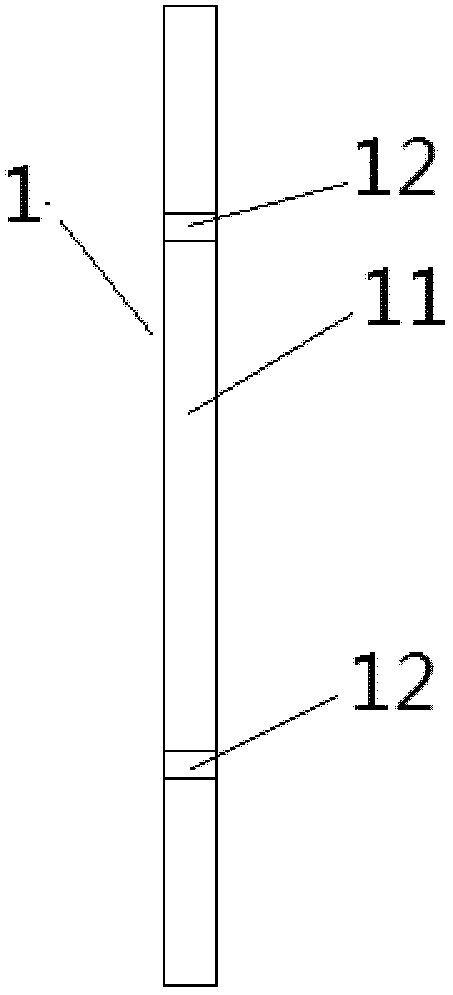
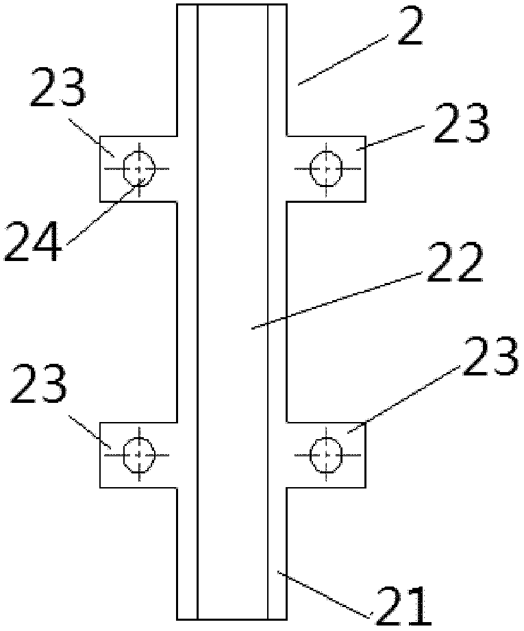
[0044] The body sheet fatigue test device provided by the present invention is mainly composed of the following parts: a fixture 4 , a centering device 1 and an anti-bending restraint device 2 . The clamp 4 is used to clamp the two ends of the fatigue sample 3, and the centering device 1 is as figure 1 and figure 2 As shown, it is used to install the fatigue sample 3 during the tension and tension-compression fatigue test, make it centered, and ensure the consistency of the installation of the same batch of fatigue samples 3. Centering device 1 includes:

[0045] The column 11 is provided with a reference plane 13 corresponding to the two clamps 4 clamped on the fatigue sample 3, and is used to keep the two clamps 4 on the same refe...


PUM


Abstract

The present invention discloses a fatigue test device for a vehicle body thin plate, and a test method thereof, and belongs to the field of material fatigue test. The test device comprises: a centering apparatus and an anti-bending constraining apparatus. The centering apparatus comprises a vertical column and two centering clamping blocks, wherein the vertical column is provided with a reference plane correspondingly attaching to holding fixtures so as to make a center line of a fatigue specimen parallel to the reference plane, and the two centering clamping blocks are intervally and vertically arranged on the reference plane of the vertical column, such that the fatigue specimen is centered to a center line of test fixtures. The test method comprises: selecting a thin plate fatigue specimen and measuring a static tension curve; carrying out calibration on test force, selecting the initial test force, and setting a condition fatigue limit of the material; adopting the fatigue test device to carry out centering and anti-bending constraining on the fatigue specimen, and adopting a testing machine to carry out a fatigue test on the fatigue specimen. According to the present invention, uniformity of the test process is ensured and influence on the tested result due to additional factors is reduced by the centering apparatus and the anti-bending constraining apparatus, the test efficiency is improved, and the test cost is saved.

Description

technical field [0001] The invention relates to the technical field of fatigue test of vehicle body thin plate materials, in particular to a vehicle body thin plate fatigue test device and a testing method, which are used for carrying out tension and tension-compression fatigue tests of vehicle body thin plate materials. Background technique [0002] The body of a car is generally welded by cold-rolled or a small amount of hot-rolled thin steel plates with a small thickness. The CAE durability analysis of the body needs the fatigue test data of the thin plate materials of the body as data input for calculation and analysis. [0003] The stress state of the body sheet in the actual working condition is in two stress states: tension or tension and compression. At present, the tests for these two stress conditions use standard material samples on the fatigue testing machine through similar wedge-shaped test fixtures. In the test, the failure of the sample usually occurs at the ...

Claims


Application Information

Patent Timeline
IPC IPC(8): G01N3/32
Inventor 陈云霞杨旋李创
Owner CHERY AUTOMOBILE CO LTD
Learn More