Mine underground cooling and waste heat recycling system
A technology of waste heat recovery and mine return air, which is applied in mine/tunnel ventilation, heat pumps, mining equipment, etc. It can solve problems such as waste of heat energy, low efficiency, and inconformity with energy saving and emission reduction, and achieves diverse and flexible forms and difficult construction And the effect of low installation cost, high economic benefit and environmental protection benefit
- Summary
- Abstract
- Description
- Claims
- Application Information
AI Technical Summary
Problems solved by technology
Method used
Image
Examples
Embodiment 1
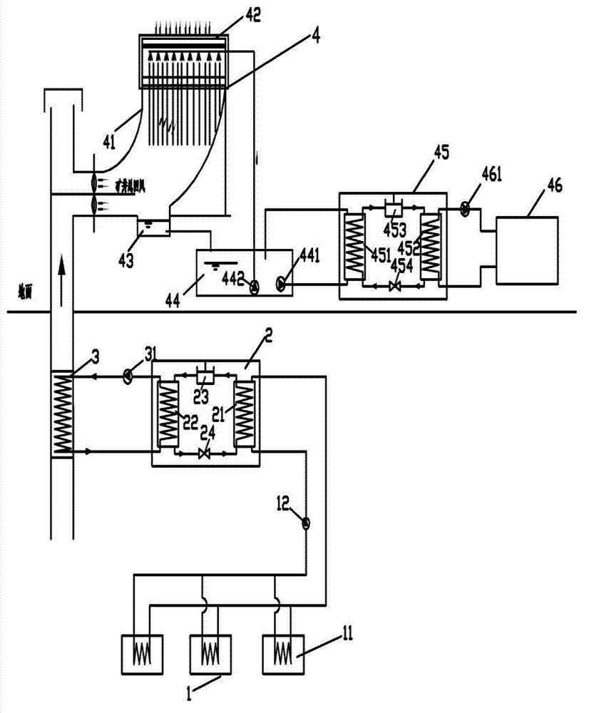
[0021] Embodiment one (such as figure 1 shown), when the mine return air heat pump system 4 is a mine return air source heat pump system, it includes a diffusion tower 41 arranged at the air outlet of the mine return airway, and a return air heat exchange unit arranged at the upper part of the air outlet of the diffusion tower 41 device 42, the sump 43 arranged at the lower part of the diffusion tower 41, the sump 44 connected with the return air heat exchanger 42 and the sump 43, the heat pump unit 45 forming a low-temperature heat source circulation loop with the sump 44 and the heat pump unit Unit 45 constitutes a consumer equipment unit 46 of the consumer heating circuit. Wherein, the heat pump unit 45 includes an evaporator 451 , a condenser 452 , a compressor 453 and an expansion valve 454 .
[0022] The working method of embodiment one is as follows:
[0023] 1) The brine in the heat exchange pipe of the air cooler 11 performs heat and moisture exchange with the downh...
Embodiment 2
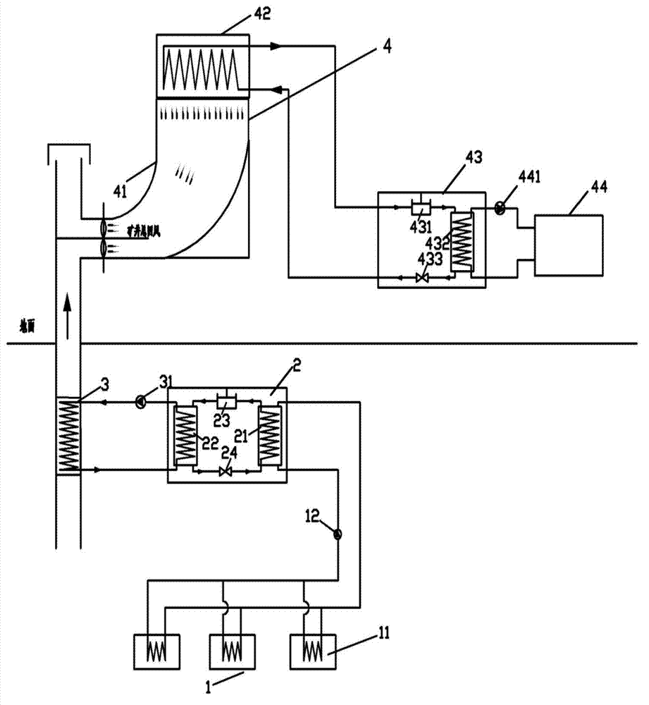
[0029] Embodiment two (such as figure 2 As shown), when the mine return air heat pump system 4 is a direct expansion mine return air source heat pump system, it includes a diffusion tower 41 arranged at the air outlet of the mine return air lane, and is arranged outside the upper part of the air outlet of the diffusion tower 41. A gas-liquid heat exchanger 42 is installed, a heat pump unit 43 forming a low-temperature heat source circulation loop with the external gas-liquid heat exchanger 42 and a user equipment unit 44 forming a user heat supply circulation loop with the heat pump unit 43 . Wherein, the heat pump unit 43 includes a compressor 431 , a built-in gas-liquid heat exchanger 432 and an expansion valve 433 .
[0030] The working method of embodiment two is basically the same as that of embodiment one, except that steps 4) to 6) are changed to the following steps 4) to 5):
[0031] 4) The mine return air absorbs heat and enters the diffusion tower 41 of the mine re...
Embodiment 3
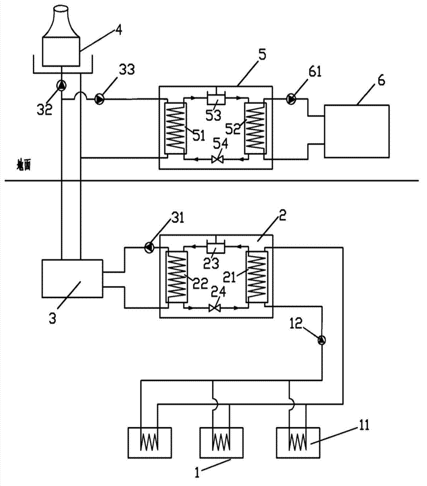
[0035] Embodiment three (such as image 3 As shown), the air cooler unit 1, the cooling unit unit 2 and the high and low pressure heat exchanger unit 3 are arranged underground in the mine, and the cooling tower 4, the heat pump unit 5 and the user equipment unit 6 are arranged above the mine.
[0036] The air cooler unit 1 can be arranged in the mining face, the driving face and the electromechanical chamber of the mine, and it includes more than one air cooler 11, and the heat exchange pipes of each air cooler 11 are filled with water or two Alcohol and other refrigerants are connected in parallel to the main pipeline connected to the evaporator 21 shell of the cooling unit unit 2 to form a refrigerant circulation loop in which a circulation pump 12 is arranged.
[0037] In the cooling unit 2, the heat exchange pipe of the evaporator 21 is filled with refrigerant, and its two ends are connected to the shell of the condenser 22 through a refrigerant output pipe and a refriger...
PUM
 Abstract
Description
Claims
Application Information
 - R&D
- Intellectual Property
- Life Sciences
- Materials
- Tech Scout
- Unparalleled Data Quality
- Higher Quality Content
- 60% Fewer Hallucinations
Browse by: Latest US Patents, China's latest patents, Technical Efficacy Thesaurus, Application Domain, Technology Topic, Popular Technical Reports.
© 2025 PatSnap. All rights reserved.Legal|Privacy policy|Modern Slavery Act Transparency Statement|Sitemap|About US| Contact US: help@patsnap.com


