
Switch with trigger

A trigger and switch technology, which is applied in the field of switches with triggers, can solve the problems of trigger current and voltage distortion, affect the electrical performance of switches, and make it difficult to realize, so as to reduce the influence of stray parameters and make the electrical connection completely reliable , resistance to ablation and heating

Active Publication Date: 2014-09-24
武汉华中华昌能源电气科技有限公司
View PDF3 Cites 0 Cited by
  • Summary
  • Abstract
  • Description
  • Claims
  • Application Information

AI Technical Summary

Problems solved by technology

[0003] However, the three-electrode trigger tube switch also has the following disadvantages: the ablation of the switch electrode material during breakdown will directly affect the performance and life of the switch; the application of the three-electrode trigger tube switch requires the use of a specially designed trigger, Moreover, the trigger is more complicated and difficult to implement.
It is especially important that the three-electrode trigger tube switch needs to properly handle the electrical connection between the switch and the trigger, otherwise it may lead to (1) a longer trigger electrical circuit, resulting in a larger impedance of the trigger circuit, which reduces the trigger current , the rise time of the trigger voltage becomes slower; (2) There are stray parameters to the ground and to the adjacent equipment in the long trigger circuit that is not connected by hard wires, which may cause the trigger current and voltage distortion, which will affect the conduction of the switch Electrical performance; in addition, it will also affect the safe use of the device, which makes the installation and use of the three-electrode trigger tube switch more complicated

Method used


Image

  • Switch with trigger
  • Switch with trigger
  • Switch with trigger

Examples


Embodiment Construction

[0022] In order to make the object, technical solution and advantages of the present invention clearer, the present invention will be further described in detail below in conjunction with the accompanying drawings and embodiments. It should be understood that the specific embodiments described here are only used to explain the present invention, not to limit the present invention.

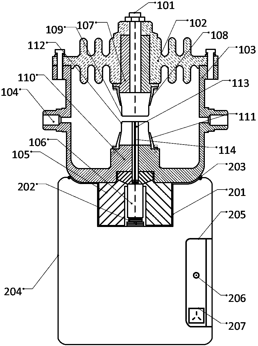
[0023] Such as figure 1 As shown, the switch with a trigger of the present invention includes a switch body 1 and a trigger 2 . The switch main body 1 includes a connection terminal 101, an insulating cover plate 102, a metal shell 103, a pair of gas nozzles 104, a cylindrical insulator 105, an extraction pole 106, an upper electrode base 107, an upper electrode sleeve 108, an upper graphite electrode 109, a lower An electrode base 110 , a lower electrode sleeve 111 , a lower graphite electrode 112 , a ceramic tube 113 , and a trigger pin 114 . The trigger 2 includes a trigger groove 201 , a trig...


PUM


Abstract

The invention discloses a switch with a trigger, which comprises a switch body and a trigger, wherein the switch body comprises a binding post, an insulating cover plate, a metal shell, a pair of air nozzles, a columnar insulator, an export pole, an upper electrode base, an upper electrode sleeve, an upper graphite electrode, a lower electrode base, a lower electrode sleeve, a lower graphite electrode, a ceramic pipe and a trigger pin; and the trigger comprises a trigger slot, a trigger output electrode, a grounding metal ring, and a functional display panel. The binding post is arranged at the center of the insulating cover plate, the insulating cover plate is connected with the metal shell to form a sealed chamber used for electrically partitioning the binding post and the metal shell, the air nozzles are symmetrically arranged on the side of the metal, and are used for charging and discharging the switch body with gas, the columnar insulator is fixed to the bottom of the switch body, the export pole penetrates through the columnar insulator along the axial direction, and the upper electrode base is connected with the insulating cover. The switch disclosed by the invention can solve the problem that a three-electrode trigger pipe type switch is electrically connected with the trigger. Moreover, the switch is compact in structure.

Description

technical field [0001] The invention belongs to the technical fields of high-voltage electrical appliances and pulse power, and more specifically relates to a switch with a trigger. Background technique [0002] In the pulse power system, the pulse power switch works under high voltage and high current, and the conditions are very harsh. The breakdown phenomenon in the switch and the physical process on the switch electrode are very complicated. Therefore, it has the ability to withstand high voltage and high current, strike The development of various switching devices with short time delay, small dispersion, small inductance and resistance, less electrode ablation, and high repetition frequency operation is a very important topic in pulse power technology. As a high-energy switching device, the three-electrode trigger tube switch is often used in transient energy conversion systems (such as electric explosion devices, electromagnetic launch devices, etc.), and as the core d...

Claims


Application Information

Patent Timeline
Patent Type & Authority Patents(China)
IPC IPC(8): H03K17/72
Inventor 李黎林福昌鲍超斌齐向东蔡礼
Owner 武汉华中华昌能源电气科技有限公司
Learn More