Capacitor energy-storage type silicon-controlled switch power supply
A technology of capacitive energy storage and switching power supply, which is applied in the direction of irreversible AC power input conversion to DC power output, and conversion equipment with intermediate conversion to AC, which can solve the problem of increased power loss of rectification and filtering circuits and large power loss of power devices , The power of a single device is small, etc., to achieve the effects of reduced energy loss, small power loss, and fast discharge speed
- Summary
- Abstract
- Description
- Claims
- Application Information
AI Technical Summary
Problems solved by technology
Method used
Image
Examples
Embodiment 1
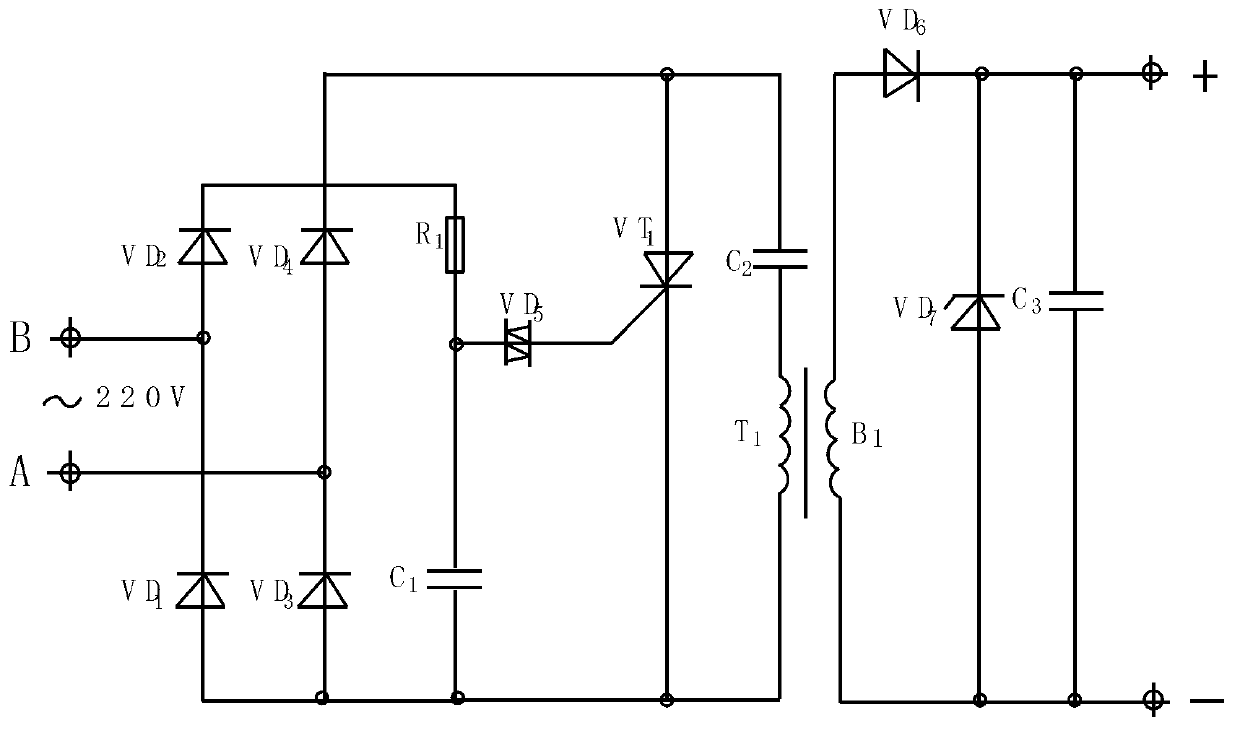
[0020] refer to figure 1 , The thyristor switching power supply is composed of capacitor charging and thyristor trigger circuit, power pulse generating circuit, and rectifying, filtering and stabilizing circuit. Diode VD 1 -VD 4 , resistance R 1 , capacitance C 1 and the diac VD 5 Constitute capacitor charging and thyristor trigger circuit. Thyristor VT 1 , capacitance C 2 and pulse transformer B 1 Constitute a power pulse generating circuit. Diode VD 6 , Zener diode VD 7 and capacitance C 3 Constitute a rectifier filter voltage regulator circuit. The thyristor switching power supply is realized through the following circuit connection, the diode VD 1 -VD 4 Constitute two separate rectifier bridges with positive poles, and the two AC input terminals A and B of the bridge are connected to the mains power supply. by VD 3 , VD 4 The positive pole in the half wall of the formed bridge is VD 4 Negative electrode, thyristor VT 1 positive electrode and storage capa...
Embodiment 2
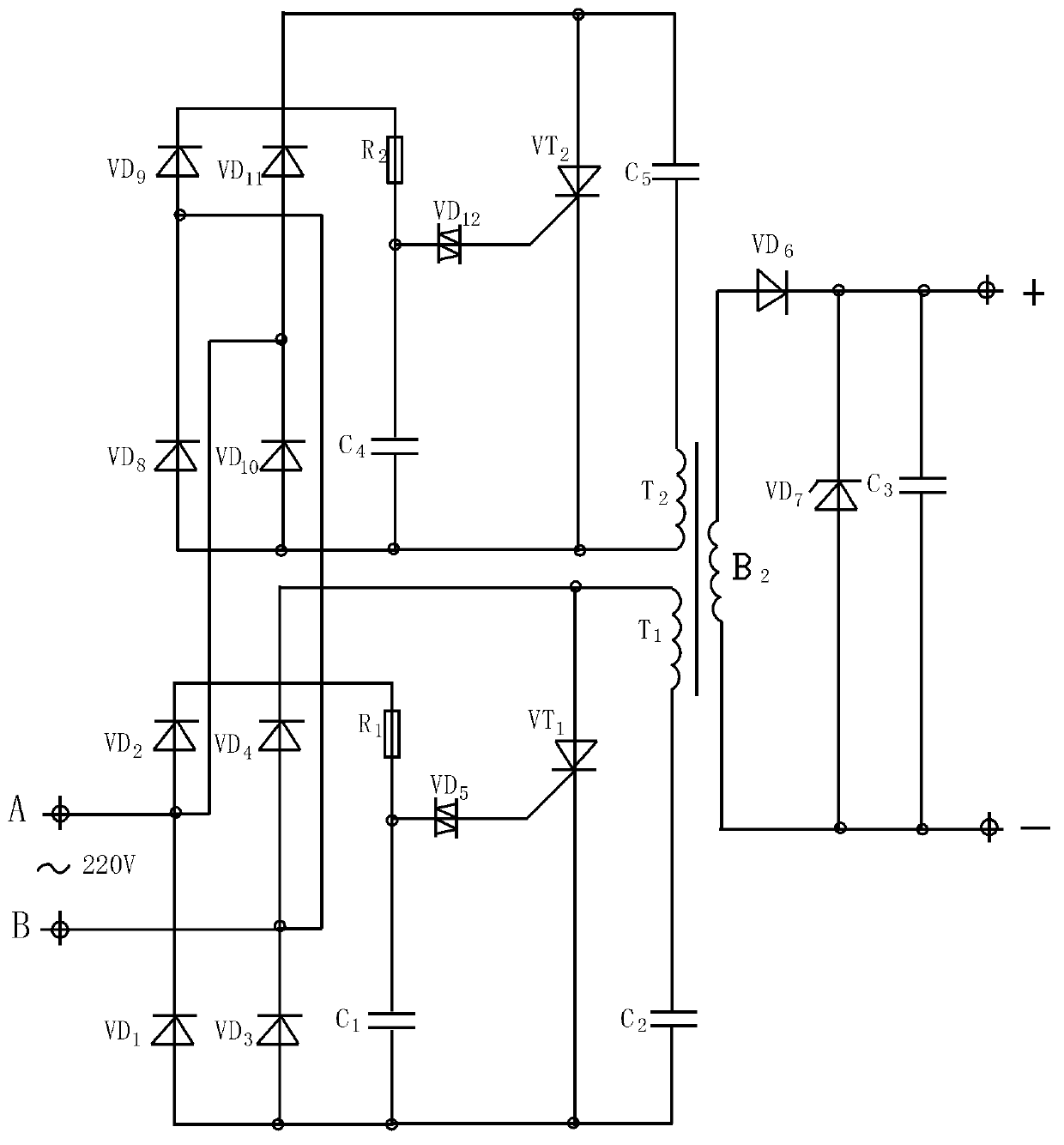
[0022] refer to figure 2 , pulse transformer B 2 There are two primary coils, one for each figure 1 Capacitor charging and silicon controlled rectifier trigger circuit and power pulse generation circuit. Both sets of circuit structures are exactly the same as the capacitor charging and thyristor trigger circuit and power pulse generating circuit in Embodiment 1, except that the half cycle of charging and triggering of one set of circuits is exactly the half cycle of triggering and charging of the other set of circuits. Therefore in the pulse transformer B 2 The pulse frequency of the secondary output is figure 1 Medium pulse transformer B 1 Twice the secondary output pulse frequency. Compared with Embodiment 1, it has the following advantages: the output power of the pulse transformer with the same magnetic core is doubled due to the doubled frequency. The power factor is improved due to the symmetry of power consumption in the upper and lower half cycles of a cycle of ...
PUM
 Abstract
Description
Claims
Application Information
 - Generate Ideas
- Intellectual Property
- Life Sciences
- Materials
- Tech Scout
- Unparalleled Data Quality
- Higher Quality Content
- 60% Fewer Hallucinations
Browse by: Latest US Patents, China's latest patents, Technical Efficacy Thesaurus, Application Domain, Technology Topic, Popular Technical Reports.
© 2025 PatSnap. All rights reserved.Legal|Privacy policy|Modern Slavery Act Transparency Statement|Sitemap|About US| Contact US: help@patsnap.com


