Micro-driving motor and lower spring for same

A technology of micro-drive motors and shrapnel, applied to circuits, electrical components, electromechanical devices, etc., can solve problems such as long welding time, unfavorable soldering, and heating of lens drive devices, and achieve high-efficiency welding methods, easy to ensure welding quality, and fast The effect of welding

Inactive Publication Date: 2015-04-22
深圳市光控数码光电有限公司
View PDF4 Cites 0 Cited by
  • Summary
  • Abstract
  • Description
  • Claims
  • Application Information

AI Technical Summary

Problems solved by technology

[0002] The existing lens driving device is also called a micro-driving motor. There is a certain gap between its conductive terminal and the circuit board, and the connection planes are perpendicular to each other. The disadvantage is that there is a certain gap between the conductive terminal of the lens driving device and the circuit board, and the connection planes are perpendicular to each other, which is not conducive to soldering, the welding time is longer, and it is easy to cause false soldering
The welding time is long, the lens driving device is easy to be heated, and it is easy to cause defects at high temperature

Method used


Image

  • Micro-driving motor and lower spring for same
  • Micro-driving motor and lower spring for same
  • Micro-driving motor and lower spring for same

Examples


Embodiment 1

[0013] (Embodiment 1, lower shrapnel assembly)

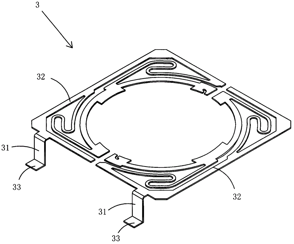
[0014] figure 1 It is a schematic three-dimensional structure diagram of the lower spring assembly in the present invention, showing a specific implementation of the coil in the present invention.

[0015] Present embodiment is a kind of spring under the miniature driving motor, see figure 1 As shown, it includes two shrapnel bodies 32 that are insulated from each other and an electrical contact pin 31 that extends vertically downward from one side of each elastic segment body 32; The electrical connection pin 31 protrudes away from the lower spring assembly 3 and forms a fixing pin 33 .

Embodiment 2

[0016] (Embodiment 2, miniature drive motor)

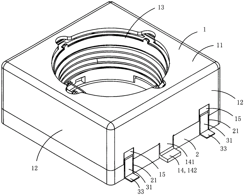
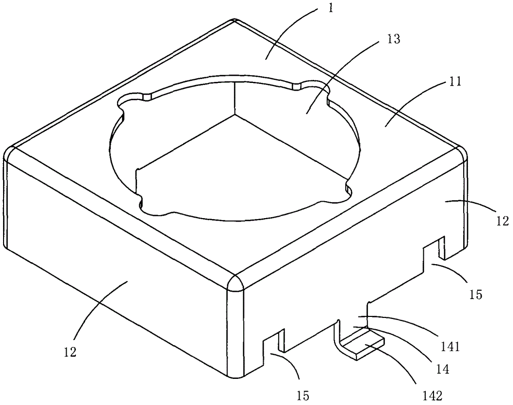
[0017] Figure 2 to Figure 4 A specific embodiment of the micro drive motor in the present invention is shown, wherein figure 2 It is a schematic diagram of a three-dimensional structure of the micro drive motor in the present invention; image 3 yes figure 2 A schematic diagram of a three-dimensional structure of the upper cover in the micro drive motor shown; Figure 4 yes image 3 A top view of the upper cover shown.

[0018] This embodiment is a kind of miniature drive motor that adopts above-mentioned embodiment 1 to make, see Figure 2 to Figure 4 As shown, it includes a housing composed of an upper cover 1 and a base 2, and a lower spring assembly 3 fixed in the housing; the upper cover 1 includes a top wall 11 and a plurality of side walls 12, and the center of the top wall 11 A light-transmitting hole 13 is provided; two opposite side walls 12 are provided with positioning feet 14 protruding vertically toward the ...


PUM


Abstract

The invention discloses a micro-driving motor and a lower spring for the same. A lower elastic piece component comprises the lower spring for the micro-driving motor which comprises two mutually insulated elastic piece bodies and electrifying pins vertically extending down from one side of each elastic piece body. The bottom end of each electrifying pin protrudingly extends perpendicular to the corresponding electrifying pin and away from the lower elastic piece component to form a fixed pin. The micro-driving motor comprises a shell and the lower elastic piece component, wherein the shell consists of an upper cover and a base, and the lower elastic piece component is fixed into the shell. The micro-driving motor and the lower spring for the same have the advantages that the fixed pins of the lower elastic component are parallel and attached to a welding face of a circuit board, and welding can be quickly completed by a simple, reliable and efficient welding mode while welding quality is easy to guarantee.

Description

technical field [0001] The invention belongs to the technical field of micro-drive motors, and in particular relates to a lower spring of a micro-drive motor and a micro-drive motor made of the shrapnel. Background technique [0002] The existing lens driving device is also called a micro-driving motor. There is a certain gap between its conductive terminal and the circuit board, and the connection planes are perpendicular to each other. The disadvantage is that there is a certain gap between the conductive terminal of the lens driving device and the circuit board, and the connection planes are perpendicular to each other, which is not conducive to soldering, the soldering time is longer, and it is easy to cause false soldering. The welding time is long, the lens driving device is easily heated, and it is easy to cause defects at high temperatures. Contents of the invention [0003] The object of the present invention is to provide a micro drive motor lower spring with be...

Claims


Application Information

Patent Timeline
Patent Type & Authority Patents(China)
IPC IPC(8): H01R12/57H02K5/22
Inventor 夏太红彭全斌
Owner 深圳市光控数码光电有限公司
Why Eureka
Try Eureka