
Method for computing ultrasonic guided-wave acoustic-elastic frequency dispersion of prestress waveguide structure

A technology of waveguide structure and ultrasonic guided wave, which is applied in computing, special data processing applications, instruments, etc., can solve problems such as lack of universality, large calculation errors, unscientific economy, etc., and achieve the effect of saving manpower and high precision

Active Publication Date: 2012-10-10
BEIJING UNIV OF TECH
View PDF2 Cites 10 Cited by
  • Summary
  • Abstract
  • Description
  • Claims
  • Application Information

AI Technical Summary

Problems solved by technology

The body wave equivalent constant method has large calculation errors for high-order modes and frequency bands with large dispersion, and sometimes even draws completely wrong conclusions; experimental calibration is greatly affected by factors such as instruments, environment, and human factors, and economically It is also unscientific, and the conclusions drawn are not universal; and because the ultrasonic guided wave has dispersion characteristics, the acoustoelastic effect changes with the change of frequency and mode. The theoretical method of dispersion calculation, and then optimize the guided wave mode and excitation frequency suitable for stress detection, which is particularly important for ultrasonic guided wave acoustoelastic stress detection

Method used


Image

  • Method for computing ultrasonic guided-wave acoustic-elastic frequency dispersion of prestress waveguide structure
  • Method for computing ultrasonic guided-wave acoustic-elastic frequency dispersion of prestress waveguide structure
  • Method for computing ultrasonic guided-wave acoustic-elastic frequency dispersion of prestress waveguide structure

Examples


Embodiment Construction

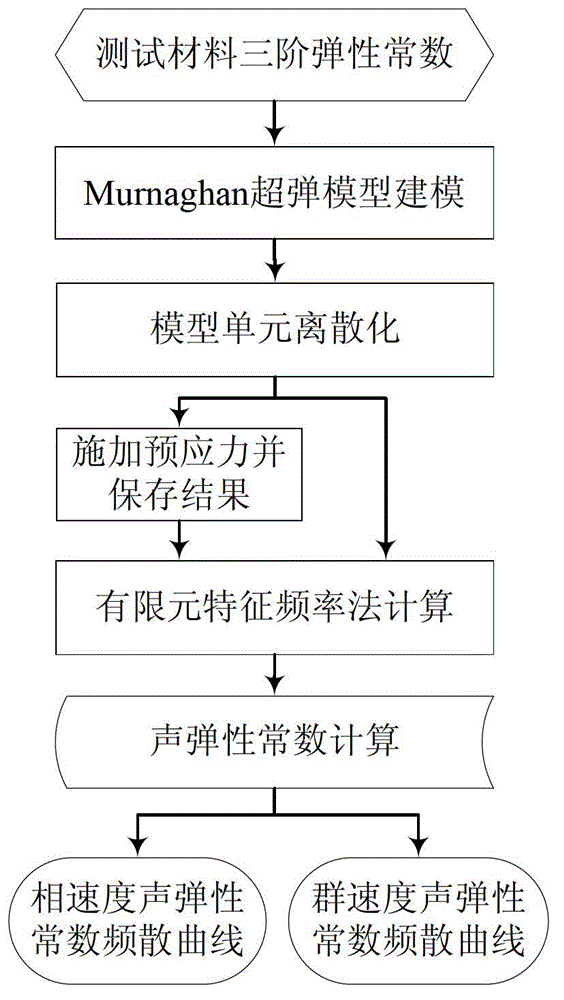
[0024] In conjunction with the content of the method of the present invention, the following example of the calculation method of the longitudinal mode acoustic elastic constant in the axisymmetric bar is provided, and the specific steps are as follows: figure 1 Shown:

[0025] 1) The material is No. 45 steel with a density of 7843kg / m 3 , using the third-order elastic constant test method of body wave, the measured second-order Lame constants are: λ=111.59GPa, μ=81.79GPa; the third-order Murnaghan constants are: l=-81.25GPa, m=-583.1GPa, n=-782.85GPa;

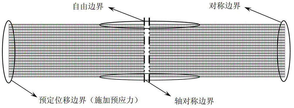
[0026] 2) Using the Murnaghan hyperelastic model to model the waveguide structure, the constitutive relation of this model is: In the formula, is the initial strain of prestress, e ζη is the acoustic small perturbation strain E γδ the linear part of . The diameter of the model is selected as 20mm, and the length of the model is selected as 1000mm;

[0027] in:

[0028] C αβγδ =C γδαβ , C αβγδζη =C αβζηγδ =C ζηαβ...


PUM


Abstract

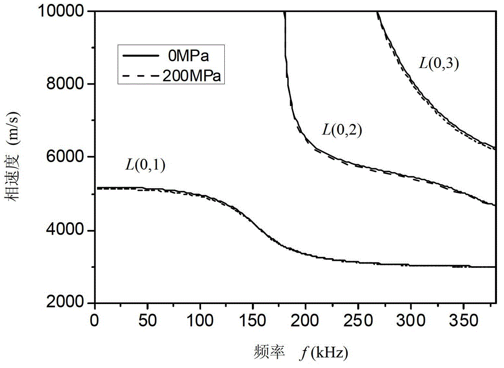
The invention discloses a method for computing ultrasonic guided-wave acoustic-elasticity frequency dispersion of a prestress waveguide structure. Based on the frequency dispersion computing theory and the Murnaghan acoustic-elasticity theory of the finite element characteristic frequency method, a super Murnaghan elastic model is introduced to the computation of characteristic frequency, prestress is loaded to the model in a form of scheduling a displacement, the loading result is stored in a material model in a form of strain energy to be an initial condition for the computation of the characteristic frequency. Phase velocity and group velocity are computed according to the finite element characteristic frequency method, a phase velocity value and a group velocity value in prestressed and stress-free conditions at identical frequencies are computed by adjacent characteristic frequency interpolation formula, and acoustic-elasticity constants of the phase velocity and the group velocity at each frequency point are computed via relative formula. By the aid of the method for computing the ultrasonic guided-wave acoustic-elasticity frequency dispersion of the prestress waveguide structure, guided-wave modality and excitation frequency suitable for acoustic-elasticity stress detection can be directly preferentially selected, and especially blank in existing theory for computing ultrasonic guided-wave acoustic-elasticity frequency dispersion is filled.

Description

technical field [0001] The invention relates to a method for calculating the acoustoelastic dispersion of ultrasonic guided waves propagating in prestressed waveguide structures (such as rods, pipes, and plates). The magnitude of the prestress is applied, and the relationship curve of the acoustic elastic constant of each mode of the ultrasonic guided wave with the frequency is obtained, and the optimal mode and excitation frequency suitable for the stress detection of the ultrasonic guided wave are optimized. Background technique [0002] Due to the advantages of fast detection speed and wide detection range, ultrasonic guided waves have been widely used to detect defects and damages in waveguide structures such as rods, plates and pipes. However, in engineering, the working stress level of such structures is more important to their health status, so it is an extremely important and challenging task to use the acoustoelastic effect of ultrasonic guided waves to detect the s...

Claims


Application Information

Patent Timeline
Patent Type & Authority Applications(China)
IPC IPC(8): G06F17/50
Inventor 吴斌刘飞何存富
Owner BEIJING UNIV OF TECH
Learn More