Eureka AIR delivers breakthrough ideas for toughest innovation challenges, trusted by R&D personnel around the world.

Novel oil pipe and application thereof

A fuel pipe, a new type of technology, applied in the direction of pipe components, oil supply devices, pipes/pipe joints/pipe fittings, etc., can solve the problems of not being able to improve power and stability, and achieve fuel saving, easy deflagration, and easy atomization Effect

Inactive Publication Date: 2012-10-10
郭荣民
View PDF8 Cites 0 Cited by
  • Summary
  • Abstract
  • Description
  • Claims
  • Application Information

AI Technical Summary

Problems solved by technology

[0003] In the prior art, there are many studies on fuel saving, and people have adopted some corresponding measures and technical means, but there are still disadvantages in its application stability and other aspects of performance, and it cannot improve its power.

Method used


Image

  • Novel oil pipe and application thereof
  • Novel oil pipe and application thereof
  • Novel oil pipe and application thereof

Examples


Embodiment 1

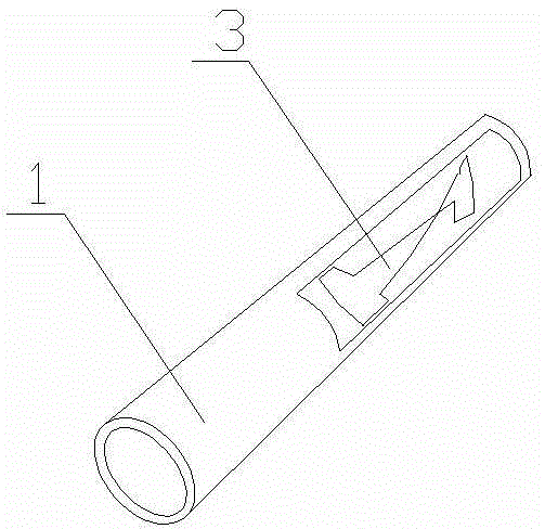
[0020] Such as figure 1 and Figure 4 As shown, a new type of oil pipe is provided with a guide device in the oil pipe 1 .

[0021] The deflector is an "I"-shaped sheet 3 in a twisted shape.

[0022] The twisted "I"-shaped piece 3 is fixed on the oil outlet or air outlet 2 of the oil pipe 1 .

Embodiment 2

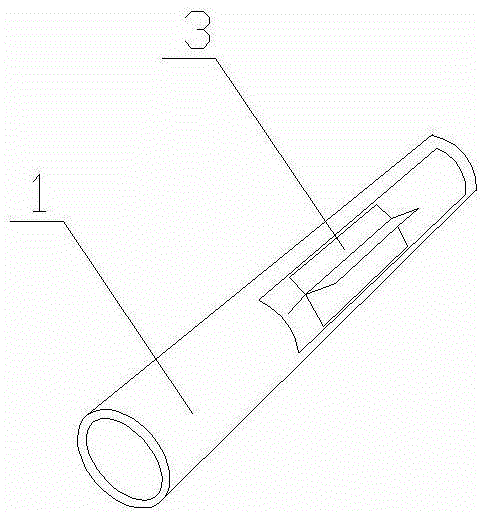
[0024] Such as figure 2 and Figure 4 As shown, a new type of oil pipe is provided with a guide device in the oil pipe 1 .

[0025] The deflector is a plurality of strip-shaped sheets 3 fixed together, and its end faces are windmill-shaped.

[0026] The windmill-shaped flow guiding device whose end face is fixed on the oil outlet or the air outlet 2 of the oil pipe 1 .

Embodiment 3

[0028] Such as image 3 and Figure 4 As shown, a new type of oil pipe is provided with a guide device in the oil pipe 1 .

[0029] The flow guiding device is that several cylinders 4 are bent and attached to the inner wall of the oil pipe 1 .

[0030] The cylinder 4 is a solid body, and the outer wall of the cylinder 4 and the inner wall of the oil pipe 1 form a cavity.

[0031] The cylinder is solid, and the outer wall of the cylinder and the inner wall of the oil pipe form a cavity.

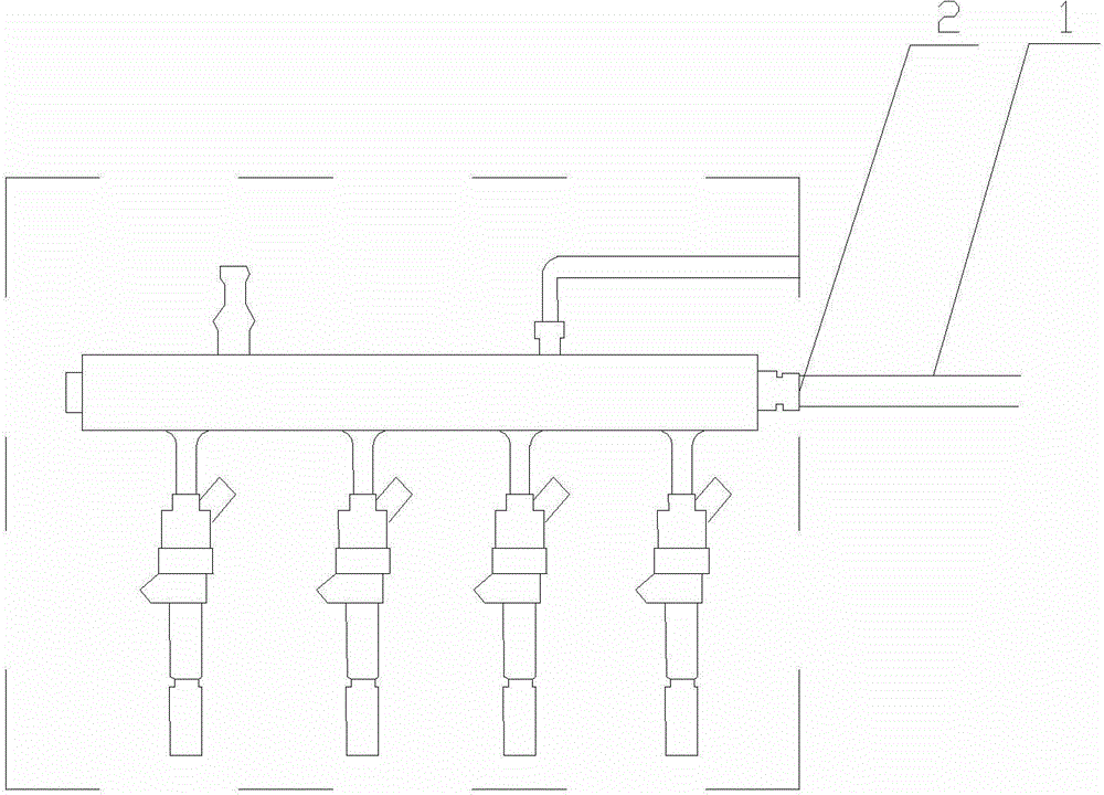
[0032] The application of a new type of oil pipe to fuel-saving and gas-saving devices on automobiles, trains, airplanes and ships.

[0033] The novel oil pipe is connected with the fuel injection rack, the fuel injection nozzle or the fuel tank on the engine.

[0034] The invention of the present invention is to add a flow guide device in the oil pipe, the flow guide device is fixed on the oil outlet or the gas outlet 2 of the oil pipe 1, and the flow guide device causes the gas or fuel t...


PUM


Abstract

The invention relates to a novel oil pile. A flow guiding device is arranged in the oil pipe, wherein the flow guiding device is a distorted I-shaped sheet; the distorted I-shaped sheet is fixed at an oil outlet or a gas outlet of the oil pipe; the flow guiding device is formed by fixing a plurality of strip-type sheets, the end surface of the flow guiding device is in a shape of a windmill, and the flow guiding device of which the end surface of the flow guiding device is in the shape of the windmill is fixed at the oil outlet or the gas outlet of the oil pipe; and the flow guiding device is formed by attaching a plurality of curved solid cylinders to the inner wall of the oil pipe, a cavity is formed between the outer walls of the cylinders and the inner wall of the oil pipe, and the novel oil pipe can be applied to an oil-saving and gas-saving device of an automobile, a plane, an airplane or a marine engine and is connected with an oil spraying frame, an oil spraying nozzle or an oil tank. The novel oil pipe has high stability, fuel oil and fuel gas are saved, energy reduction effect is obvious, and power can be effectively increased.

Description

technical field [0001] The invention relates to an oil pipe, in particular to a new type of oil pipe that atomizes gas and fuel to save fuel and air, and is applied to industries such as automobiles, trains, airplanes, and ships. Background technique [0002] With the continuous increase of the number of vehicles, on the one hand, the exhaust gas will cause great pollution to the environment, and on the other hand, the consumption of oil will increase sharply. As a "gold" resource, the storage capacity of oil is gradually decreasing, and because of its The renewable speed is extremely slow, so it is imperative to improve the utilization rate of oil, save fuel and reduce energy consumption. [0003] In the prior art, there are many researches on fuel saving, and people have adopted some corresponding measures and technical means, but there are still disadvantages in the performance of various aspects such as the stability of its application, and its power cannot be improved. ...

Claims


Application Information

Patent Timeline
IPC IPC(8): F02M21/02F02M37/00F02M55/02F16L55/00
CPCY02T10/32Y02T10/30
Inventor 郭荣民
Owner 郭荣民
Why Eureka
Eureka Blog
Learn More