
Overflow pipe and slurry tank using same

A technology of overflow pipe and slurry tank, which is applied in the field of rotatable overflow pipe and slurry tank using the overflow pipe, which can solve the problem of inconsistency in flow velocity of slurry, time-consuming and inability to match the ratio of downstream raw material formula and other issues to achieve the effect of avoiding potential safety hazards

Active Publication Date: 2012-10-10
GUIGANG BATIAN ECOLOGY
View PDF6 Cites 2 Cited by
  • Summary
  • Abstract
  • Description
  • Claims
  • Application Information

AI Technical Summary

Problems solved by technology

[0003] When changing production and changing the product formula, the slurry of the previous formula in the tank needs to be completely emptied by opening the bottom discharge valve. The gap with the valve seat is small, it is easy to enter crystals and impurities to block the valve, and it cannot be opened or closed smoothly. Sometimes it needs to be manually blown with steam, which is labor-intensive and time-consuming. Improper operation may also be scalded by the sprayed slurry. security risks
At the same time, during the discharge process, the liquid level of the slurry in the tank changes, and the pressure of the slurry also changes accordingly. Under the same valve opening, the flow rate of the slurry is inconsistent, and it cannot be matched with the downstream raw materials according to the formula. Proportion matching, which is likely to cause unqualified products that are converted to production

Method used

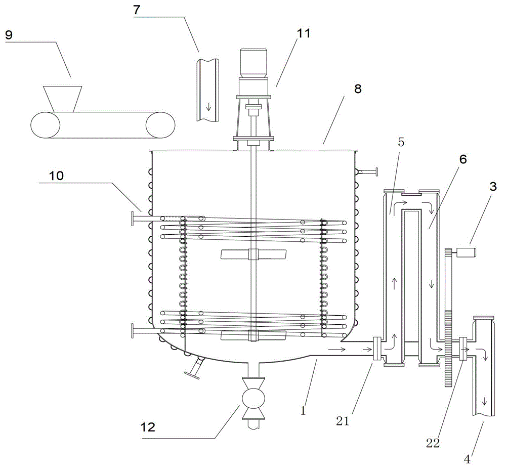

Image

  • Overflow pipe and slurry tank using same

Examples


Embodiment Construction

[0016] Examples of the present invention are figure 1 As shown, an overflow pipe includes an overflow main pipe 1, rotary sealing joints 21 and 22, a control structure and a discharge pipe 4, and the two ends of the overflow pipe are respectively provided with an overflow inlet pipe 5 and an overflow outlet pipe 6. The overflow inlet pipe 5 and the overflow outlet pipe 6 are respectively connected to the rotary sealing joints 21 and 22; the rotary sealing joint 21 of the overflow inlet pipe 5 is used to connect with the slurry tank 7, and the rotary sealing of the overflow outlet pipe 6 The joint 22 is used to connect with the discharge pipeline 4; the control structure is arranged at either end of the overflow pipe, and the control structure controls the rotation of the overflow main pipeline 1 according to the liquid level of the slurry in the slurry tank 7, so that the overflow main pipeline The level at the top of the pipeline 1 is equal to the liquid level of the slurry i...


PUM


Abstract

The invention relates to an overflow pipe and a slurry tank using the same. The overflow pipe comprises an overflow main pipe, rotary sealing joints, a control structure and a drainage pipe, and an overflow inlet pipe and an overflow outlet pipe are respectively arranged at two ends of the overflow pipe, and are respectively connected with the rotary sealing joints; the rotary sealing joint of the overflow inlet pipe is connected with the slurry tank, and the rotary sealing joint of the overflow outlet pipe is connected with the drainage pipe; and the control structure is arranged at an optional end of the overflow pipe, and controls rotation of the overflow main pipe according to the liquid level of slurry in the tank, so that the horizontal height of the top of the overflow main pipe isflush with the liquid level of the slurry in the tank. By the overflow pipe and the slurry tank using the same, potential safety hazards caused by manual operation are reduced while automatic production level and yield of compound fertilizers are increased.

Description

technical field [0001] The invention relates to an overflow pipe and a slurry tank using the overflow pipe, in particular to a rotatable overflow pipe used in the field of producing compound fertilizers by a high-tower process and a slurry tank using the overflow pipe Can. Background technique [0002] The production of NPK compound fertilizer by the existing high-tower process generally adopts a tank with a built-in steam heating coil. During the working process, a feeder or a slurry pipe is used to put solid powder or liquid slurry into the tank. The inside is heated by the coil and stirred by the mixer, and the material is continuously fed into the tank. When the slurry reaches a certain height, the slurry flows out from the fixed overflow pipe, and the material must be continuously fed. Due to the overflow, the slurry in the tank The liquid level can be maintained at the overflow position to ensure the smooth flow of slurry. [0003] When changing production and changi...

Claims


Application Information

Patent Timeline
Patent Type & Authority Applications(China)
IPC IPC(8): C05G1/00
Inventor 张运森王春建
Owner GUIGANG BATIAN ECOLOGY
Learn More