
Compression roller safety control device

A technology of safety control and pressing roller, applied in the direction of controlling lamination, lamination, chemical instruments and methods, etc., it can solve the methods and cases where the relationship between safety and production is not seen, and it is easy to be brought under the pressing roller by the film belt to be pressed. Injury, the stainless steel retaining pipe is difficult to do sanitation and other problems, to achieve the effect of automatic safety protection, fast response speed, convenient installation and promotion

Inactive Publication Date: 2015-02-04
HUBEI LHTC ANTI COUNTERFEITING TECH CO LTD
View PDF6 Cites 0 Cited by
  • Summary
  • Abstract
  • Description
  • Claims
  • Application Information

AI Technical Summary

Problems solved by technology

[0002] With the continuous development of science and technology, technologies in different fields have begun to integrate with each other, especially optoelectronic technology and traditional mechanical technology and control technology are constantly and deeply combined. Infrared control technology combines infrared optical technology with control technology to form such as Infrared alarms are increasingly used in safety precautions, system failure alarms, etc. In the production process of laser anodized aluminum films, polyester films called film tapes are mostly used as base films, and evenly coated on them Cloth one or more layers of coatings with different chemical properties, and then use the hot molding process to complete the entire production process. On the molding presses used in the existing molding process, there are plate rolls, cooling rolls, and preheating rolls, which can be collectively referred to as They are work rolls. On the sides of these work rolls, pressure rolls are arranged side by side. When there are dirty spots on the work rolls or pressure rolls, the operator should hold a rag to wipe them off. If these work rolls are dirty when they are rotating Point, because of its high-speed rotation, the operator's hand is easily brought under the pressure roller by the film belt and crushed, and the pressure roller may even break the fingers. In the current production, various methods are used for safety precautions, such as using a stainless steel The square tube is used to block the film inlet to solve the problem, but it brings new problems. The working environment of molding requires cleanliness to avoid dust and dirt from contacting the film tape, which will affect the quality of the film tape. Therefore, it is cleaned regularly every day. The stainless steel retaining tube makes it difficult to do sanitation, and it also brings inconvenience to maintenance. In addition, the stainless steel square tube also has a certain degree of elasticity, which may not be able to stop the danger of the hand being brought into the press roller by the high-speed film belt at critical times.
Engineers and technicians also thought of adopting the method of infrared alarm, and because the simple alarm device and directly cutting off the power supply will cause the equipment to stop production, a section of defective products will be produced, the product quality will be greatly adversely affected, and at the same time affect the quality of the next process. Normal production, so the existing direct power-off infrared alarm device is not used. How to coordinate and solve the relationship between safety and production, so as to solve the defect of imperfect safety protection in the current production technology, is an urgent need for engineering and technical personnel to solve Problem; In the prior art, there is no method and case for adopting the method of the present invention to solve the relationship between safety and production

Method used

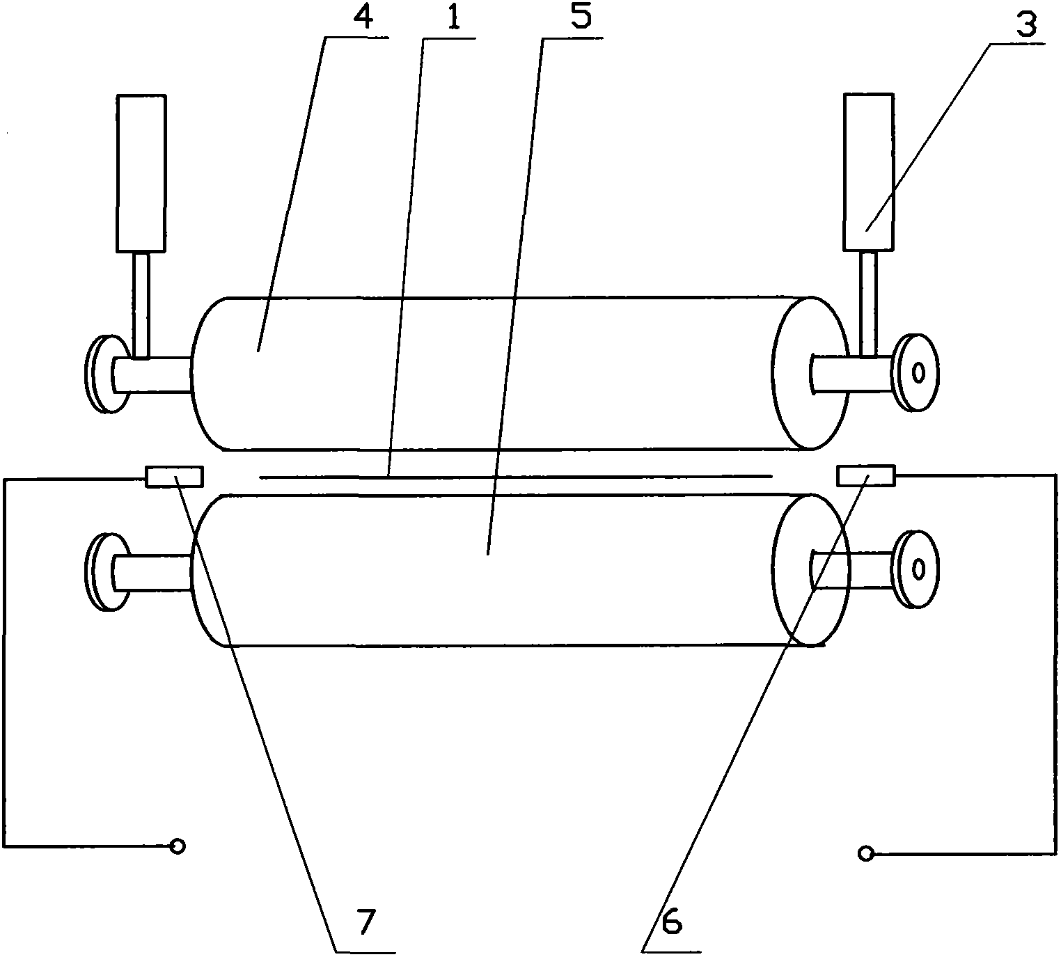
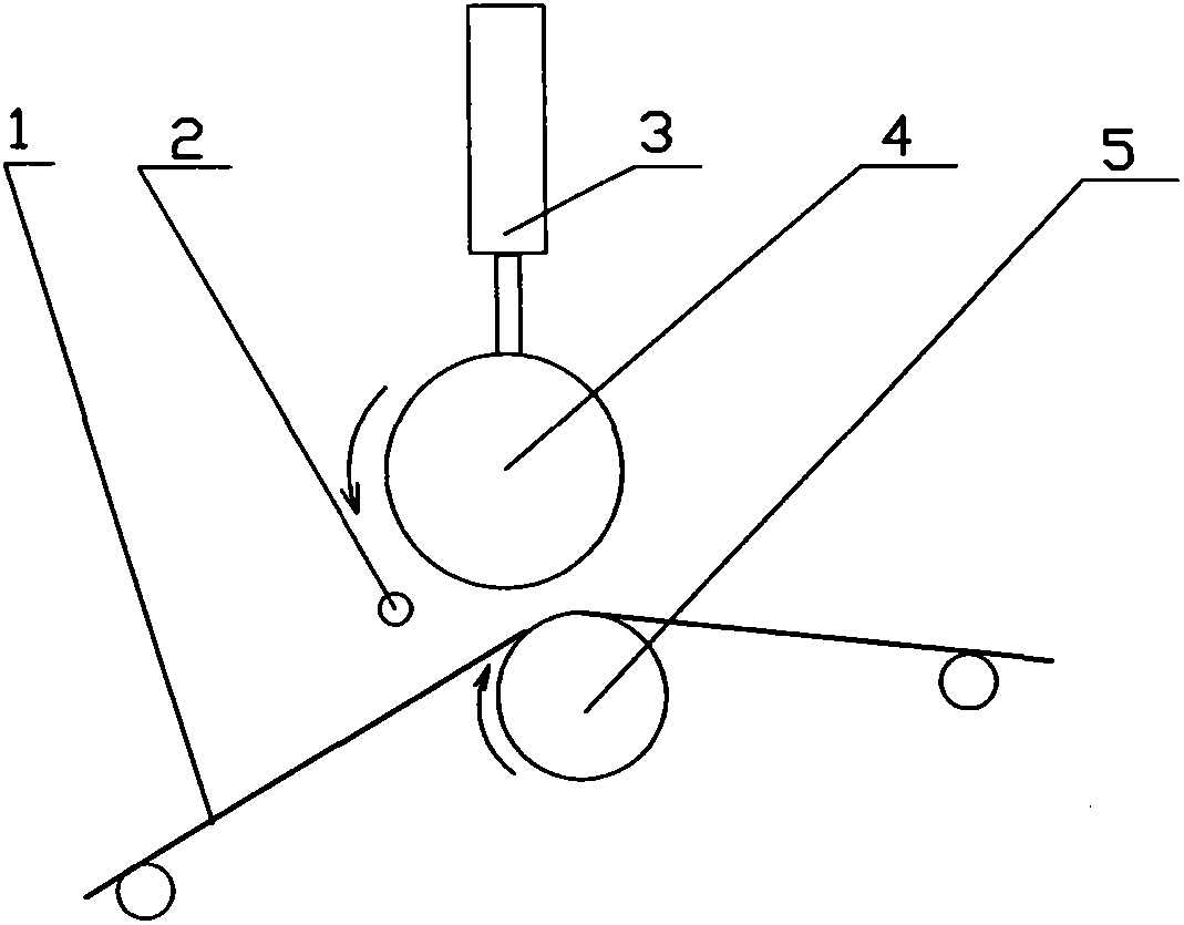
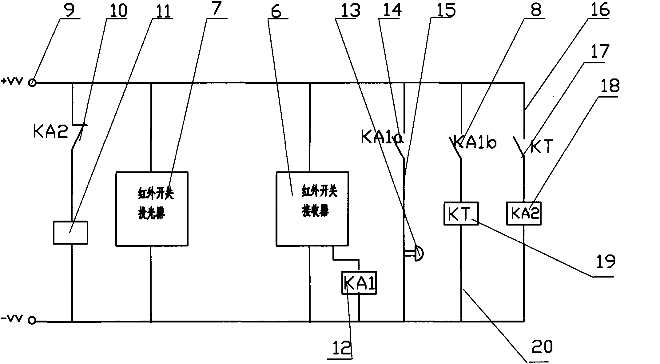

Image

  • Compression roller safety control device
  • Compression roller safety control device
  • Compression roller safety control device

Examples


Embodiment Construction

[0015] The present invention will be described in detail below in conjunction with specific embodiment and comparative example:

[0016] The present invention utilizes the infrared photoelectric switch and double protection, taking into account the dual purposes of safety and production. Considering the two directions of safety and production, the embodiments can be combined arbitrarily under the premise of achieving the above purpose, and are not limited to the following specific disclosures Example.

[0017] The molding machine of the prior art does not use an infrared safety protection device, and the action of the original pressure roller is realized by the electromagnetic reversing valve 11 connected in series in the circuit. The existing technology is: when the production starts and the pressure roller 4 needs to be pressed together , the working power supply 9 supplies power, the electromagnetic reversing valve 11 is energized, and the electromagnetic reversing valve 11...


PUM


Abstract

The invention relates to a block press device for a printing industry and especially relates to a compression roller safety control device. The compression roller safety control device realizes dual protection by a production safety alarm and a safety protection action and improves a yield and production efficiency of molding production. Infrared optoelectronic switches comprising infrared switch light-projectors and infrared switch receivers are respectively arranged at corresponding positions between a compression roller and a working roller of a block press, at two ends of the compression roller at a rolling side of a film strip, and at two edges which can travel closely to the film strip. A normally-closed contact of a relay coil KA2 is connected to a coil of a magnetic exchange valve in series. A working power supply of the magnetic exchange valve supplies power to the infrared optoelectronic switches simultaneously. The compression roller safety control device has dual effects of safe production and safety protection, realizes warning and shutdown when secondary power failure, enables operators to have chances of carrying out safety measures and correcting error actions under warning, clears a safety alarm when an error is corrected, and avoids any shutdown processes thereby avoiding defective good problems caused by shutdown.

Description

technical field [0001] The invention relates to molding press equipment in the printing industry, in particular to a pressure roller safety control device. Background technique [0002] With the continuous development of science and technology, technologies in different fields have begun to integrate with each other, especially optoelectronic technology and traditional mechanical technology and control technology are constantly and deeply combined. Infrared control technology combines infrared optical technology with control technology to form such as Infrared alarms are increasingly used in safety precautions, system failure alarms, etc. In the production process of laser anodized aluminum films, polyester films called film tapes are mostly used as base films, and evenly coated on them Cloth one or more layers of coatings with different chemical properties, and then use the hot molding process to complete the entire production process. On the molding presses used in the exi...

Claims


Application Information

Patent Timeline
Patent Type & Authority Patents(China)
IPC IPC(8): B32B41/02
Inventor 汪俊
Owner HUBEI LHTC ANTI COUNTERFEITING TECH CO LTD
Learn More