


Quick Research
Generate reliable direction feasibility study reports for your R&D in just a few steps.

Technical Q&A
Discover and master advanced knowledge NOW. Basics, ideas, possibilities, all at once.

Find Solutions
As an expert in R&D theories, this can generate solutions to your technical problems instantly.

Evaluate Feasibility
Analyze your overall solution with one click, know your potential R&D risks in advance.

Monitor Landscape
Get weekly tech updates, stay abreast of the latest tech innovations and key insights.
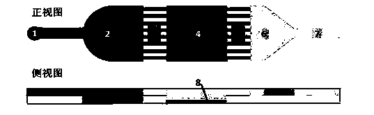
Triggerable and disposable microchip liquid pump based on chemical reaction
A chemical reaction and microchip technology, applied in chemical instruments and methods, chemical/physical processes, chemical/physical/physicochemical processes, etc., can solve problems such as uncertainty, analysis results, etc.
- Summary
- Abstract
- Description
- Claims
- Application Information
AI Technical Summary
Problems solved by technology
Method used
Image


Examples
Embodiment 1
[0027] Step 1. Expose the glass chromium plate with a patterned film (the pattern includes the middle pump chamber and the driving U pipeline at the back, refer to 9 and 10 in the accompanying drawing), and then use 1mol / L HF acid solution to Etching for 0.5 hours and 4 hours serves as a template for the upper and lower PDMS sheets.
[0028] Step 2. Mix polydimethylsiloxane (PDMS) and curing agent at a ratio of 5:1, pour it on the glass mold, use a vacuum pump to remove air bubbles, and heat in an oven at 100°C for 0.2 hours to make PDMS Curing, and then peeling off from the mold to make the top and bottom PDMS sheets, punch holes with a puncher at the exit of the top PDMS sheet as the top sheet of PDMS.
[0029] Step 3. Add 0.1 μL of fluorosilane solution dropwise to the middle tank of the solid on the PDMS top sheet, and dry it under an infrared lamp.
[0030] Step 4. Put plastic tape on the PDMS bottom piece, and add NaHCO in the middle slot 3 , so that it is firmly attac...
Embodiment 2
[0035] Step 1. Expose the glass chromium plate with a patterned film (the pattern includes the middle pump chamber and the driving U pipeline at the back, refer to 9 and 10 in the accompanying drawing), and then use 1mol / L HF acid solution to Etching for 0.5 hours and 4 hours serves as a template for the upper and lower PDMS sheets.
[0036] Step 2. Mix polydimethylsiloxane (PDMS) and curing agent at a ratio of 10:1, pour it on the glass mold, use a vacuum pump to remove air bubbles, and heat it in an oven at 60°C for 2 hours to make PDMS Cured, peeled off from the mold, and punched with a puncher at the outlet, as a PDMS top sheet.
[0037] Step 3. Add 0.5 μL of fluorosilane solution dropwise to the middle tank of the solid on the PDMS top sheet, and dry it under an infrared lamp.
[0038] Step 4. Put plastic tape on the PDMS bottom piece, and add CaCO in the middle slot 3 , so that it is firmly attached to the surface of the tape.
[0039] Step 5. Paste a plastic sheet on...
Embodiment 3
[0043] Step 1. Expose the glass chromium plate with a patterned film (the pattern includes the middle pump chamber and the driving U pipeline at the back, refer to 9 and 10 in the accompanying drawing), and then use 1mol / L HF acid solution to Etching for 0.5 hours and 4 hours serves as a template for the upper and lower PDMS sheets.
[0044] Step 2. Mix polydimethylsiloxane (PDMS) and curing agent at a ratio of 8:1, pour it on the glass mold, use a vacuum pump to remove air bubbles, and heat it in an oven at 80°C for 1 hour to make PDMS Cured, peeled off from the mold, and punched with a puncher at the outlet, as a PDMS top sheet.
[0045] Step 3. Add 0.3 μL of fluorosilane solution to the middle tank of the solid on the PDMS top sheet, and dry it under infrared light.
[0046] Step 4. Put plastic tape on the bottom of PDMS, and add CaHCO in the middle slot 3 , so that it is firmly attached to the surface of the tape.
[0047] Step 5. Paste a plastic sheet on the solid groo...
PUM
 Abstract
Description
Claims
Application Information
 - R&D Engineer
- R&D Manager
- IP Professional
- Industry Leading Data Capabilities
- Powerful AI technology
- Patent DNA Extraction
Browse by: Latest US Patents, China's latest patents, Technical Efficacy Thesaurus, Application Domain, Technology Topic, Popular Technical Reports.
© 2024 PatSnap. All rights reserved.Legal|Privacy policy|Modern Slavery Act Transparency Statement|Sitemap|About US| Contact US: help@patsnap.com