Eureka AIR delivers breakthrough ideas for toughest innovation challenges, trusted by R&D personnel around the world.

Method for constructing CAM (computer-aided manufacturing) system for punching for automobile girders

A technology of automobile longitudinal beams and construction methods, applied in general control systems, control/adjustment systems, instruments, etc., can solve the problems of backward control, high error rate, and unintuitiveness of the punching CAM system, so as to speed up the production cycle and reduce redundancy. The effect of little time left

Active Publication Date: 2012-10-03
广州市力鼎汽车零部件有限公司
View PDF5 Cites 13 Cited by
  • Summary
  • Abstract
  • Description
  • Claims
  • Application Information

AI Technical Summary

Problems solved by technology

[0004] The above various programming control methods have low efficiency, high error rate, many steps, and cumbersome, once the graphics are changed, they have to start all over again.
There are the following three types of disadvantages: (1) programmers need to learn and master the CNC language, (2) need to convert the information of the processed parts into text or digital information, which is not only not intuitive, but also has a high error rate during the conversion process, (3) NC language programming still adopts batch processing at present, that is, the part source program written in NC language is only processed once after being input into the computer, and manual intervention cannot be performed during the processing, so that the operation result of the instruction code cannot be modified. Vehicle stringers for remodeled and pre-production models require frequent revisions
[0005] Due to the limitations of the above-mentioned control software, the control of the punching CAM system is backward, and the technical performance, versatility and efficiency are relatively poor

Method used


Image

  • Method for constructing CAM (computer-aided manufacturing) system for punching for automobile girders
  • Method for constructing CAM (computer-aided manufacturing) system for punching for automobile girders
  • Method for constructing CAM (computer-aided manufacturing) system for punching for automobile girders

Examples


Embodiment Construction

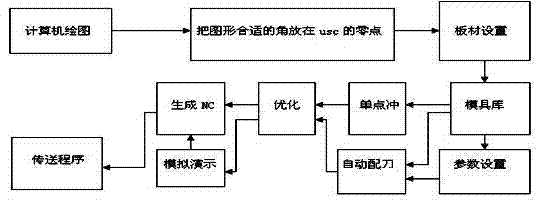
[0060] A CAM system for the punching process of the longitudinal beam of the automobile is characterized in that it includes:

[0061] 1. A device for reading CAD files.

[0062] Including computer hardware and operating system, CAD system, module for deleting duplicates, module for obtaining CAD data, module for screening and separating data and data storage module.

[0063] 2. A device for establishing links, icon menus and interfaces in the CAD / CAM system.

[0064] Including ActiveX Automation technology, visual Basic main program, VBA link program, scripts (Scripts), icon menu database and SETUP installation program.

[0065] 3. A device that converts the data in the CAD file into the mold model and dimension data of the CAM system.

[0066] Including mold database, plate setting module, tolerance setting module, data storage module and CAM generation module.

[0067] 4. Mold adaptation, optimization and simulation operation device.

[0068] It includes a dead zone jud...


PUM


Abstract

A method for constructing a CAM (computer-aided manufacturing) system for punching for automobile girders is characterized by including selecting the types of used numerical-control punching production lines for the automobile girders; creating projects corresponding to the types of the numerical-control punching production lines for the automobile girders, building mathematical models of algorithms, and building generic modules; determining the types of the projects as Activex DII and compiling the types of the projects into types of dynamic linking libraries; writing and compiling interface programs connected with the dynamic linking libraries by VBA (visual basic for application); writing scripts for the various types of numerical-control punching production lines, and creating a CAM icon menu file and icons corresponding to various items; packaging various documents such as the CAM icon menu file, the interface programs written by the VBA, each class-generation DLL (dynamic linking library) compiled by VB (visual basic), development interfaces provided in the form of VB types, windows, the modules, the projects, an encryption method and instructions in a SETUP to form installation programs of the various types of numerical-control punching production lines for the automobile girders; and adding a CAM menu into a menu self-defining term in a CAD (computer-aided design).

Description

[0001] This application is a divisional application of the invention patent application with the application date of November 27, 2009, the application number 200910230972.9, and the title of "CAM system, control method and construction method for punching of automobile longitudinal beams". technical field [0002] The invention relates to the technical fields of a numerical control punching production line control system and computer-aided manufacturing (CAM), in particular to an automobile longitudinal beam CAM system, a control method, and a system construction method for automobile modified and trial-manufactured models. Background technique [0003] At present, the CAD / CAM integrated software with CNC programming function used in the world for stamping equipment mainly includes PROCAM software from TEKSOFT in the United States, NEWCAM from Taiwan Shixin Technology, AP100 from Amada Corporation in Japan, and other CAM automatic programming software. CNC machining function...

Claims


Application Information

Patent Timeline
Patent Type & Authority Applications(China)
IPC IPC(8): G05B19/4097
Inventor 韩学军丁涛刘振堂赵加蓉李永刚
Owner 广州市力鼎汽车零部件有限公司
Why Eureka
Eureka Blog
Learn More