High-rigid clamp of testing machine

A testing machine and high-rigidity technology, applied in the direction of strength characteristics, measuring devices, instruments, etc., can solve the problems of difficult alignment, changing the installation position of the curved jaws, and scrapping of the curved jaws, so as to prolong the service life. , The effect of reducing economic loss and convenient sample clamping

Inactive Publication Date: 2012-10-03
JINAN KEHUI TESTING INSTR
View PDF6 Cites 0 Cited by
  • Summary
  • Abstract
  • Description
  • Claims
  • Application Information

AI Technical Summary

Problems solved by technology

[0002] The clamp body used in the tensile test of metal materials adopts the traditional arc-shaped jaw clamping plate. Due to the left-right symmetrical guiding structure of the traditional arc-shaped jaw clamping plate, the semi-open jaw seat cannot be placed behind the wedge-shaped jaw. Install the pressure plate, so the arc-shaped jaw clamping plate is no longer suitable for use in the semi-open jaw seat, and the arc-shaped jaw that matches it is different from the arc-shaped jaw clamping plate in terms of length and size. It is not easy to center when installing in the plate, and each clamping and unloading of the sample will cause the installation position of the arc-shaped jaw to change, so that the coaxiality of the tested sample cannot be guaranteed, which affects the test results. The traditional arc-shaped jaw The clamping plate is directly connected with the push plate, and the connecting surface of the clamping plate is easily deformed after repeated use, which makes the curved clamping plate scrapped
Currently, there is no good solution

Method used


Image

  • High-rigid clamp of testing machine
  • High-rigid clamp of testing machine
  • High-rigid clamp of testing machine

Examples


Embodiment Construction

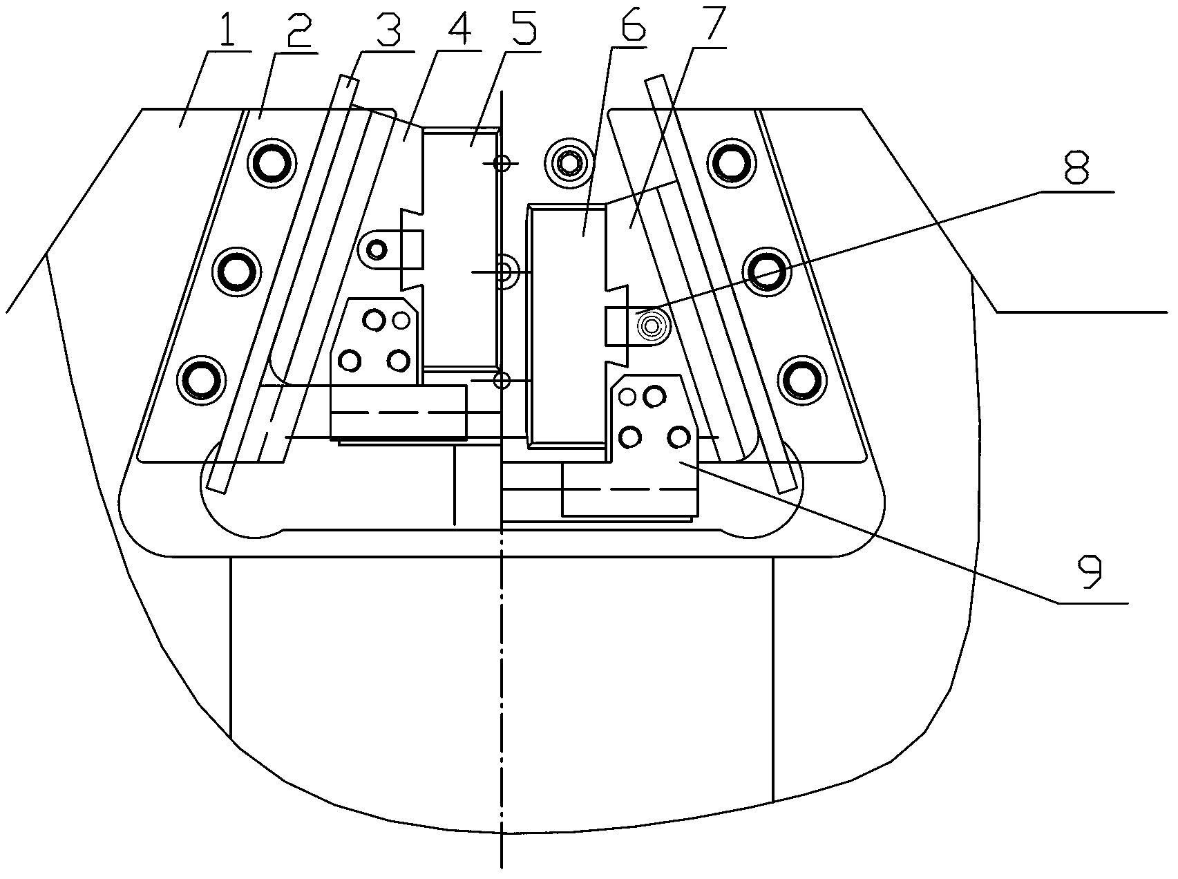
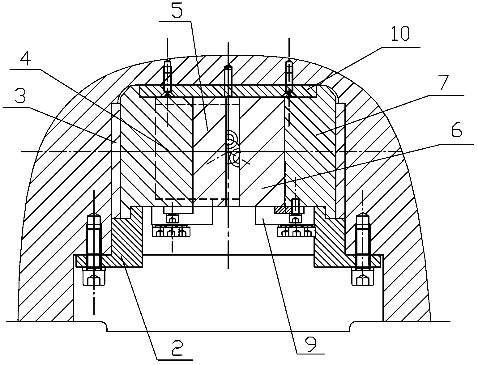
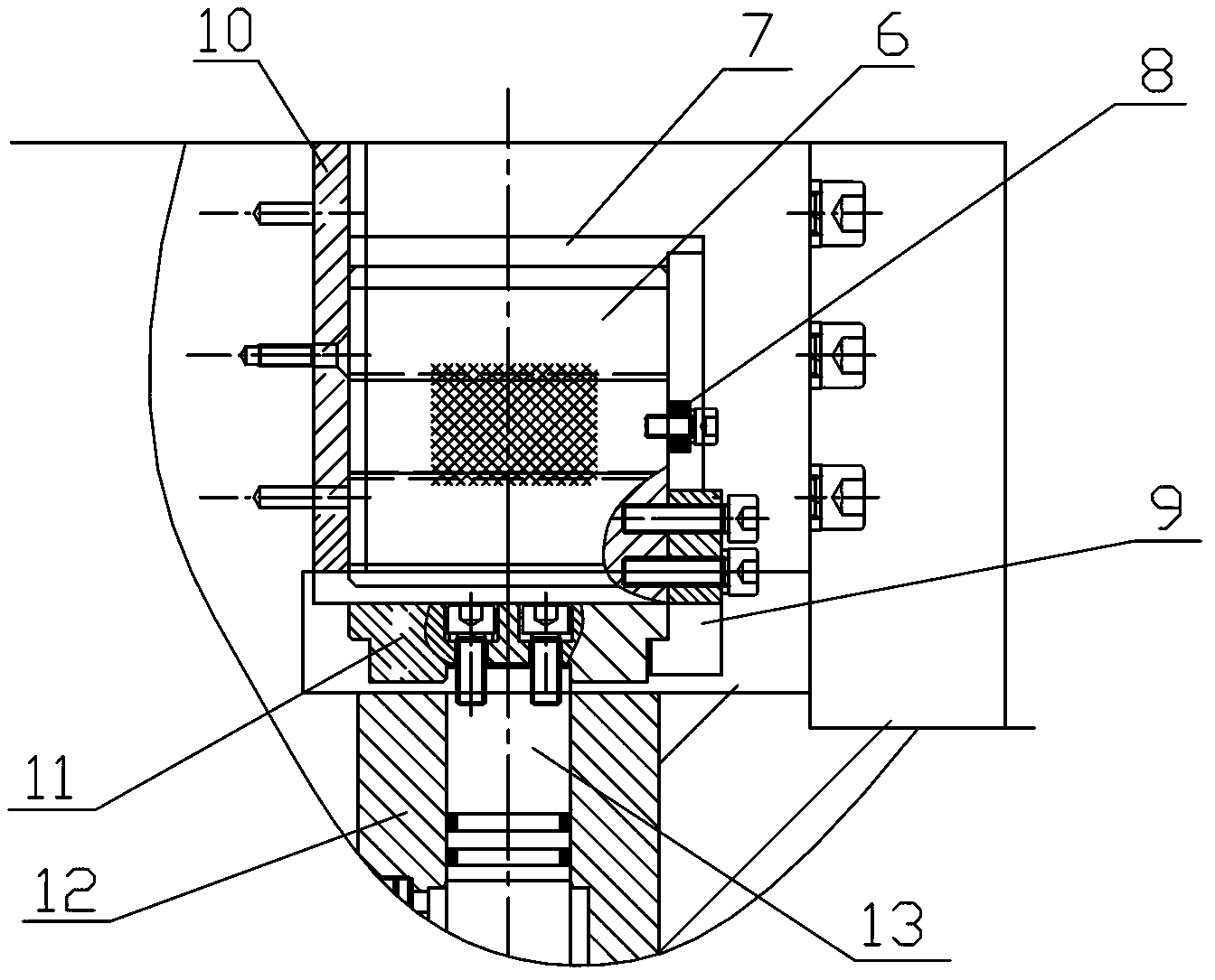
[0015] Refer to the attached figure 1 To attach Figure 7 The high-rigidity testing machine grip body of the present invention will be described in detail below.

[0016] The clamp body of the high-rigidity testing machine of the present invention has a structure comprising a jaw seat 1, a jaw clamping plate, a jaw, a push plate 11, a piston 13 and an oil cylinder 12, and the jaws include a left jaw 5 and a right jaw 6 , the jaw clamping plate includes a left jaw clamping plate 4 and a right jaw clamping plate 7, the oil cylinder 12 is arranged on the bottom of the push plate 11, and the piston 13 in the oil cylinder 12 is connected with the push plate 11 by screws, The jaw seat 1 is a semi-open jaw seat, the jaws are in the same size as the jaw clamping plate, the gap between the left jaw 5 and the left jaw clamping plate 4 and between the right jaw 6 and the right jaw The dovetail type fit is respectively adopted between the jaw clamping plates 7, and the described push pl...


PUM


Abstract

The invention discloses a high-rigid clamp of a testing machine, which belongs to a clamp. The high-rigid clamp comprises a jaw seat, jaw clamp plates, jaws, a push plate, a piston and an oil cylinder, wherein the jaws include a left jaw and a right jaw; the jaw clamp plates include a left jaw clamp plate and a right jaw clamp plate; the jaw seat is in a half-opening type; the left jaw and the left jaw clamp plate are matched in a dovetailed mode, and the right jaw and the right jaw clamp plate are matched in a dovetailed mode; the push plate is respectively connected with the lower sides of the left and right jaw clamp plates through a connection plate; pressing plates are respectively arranged in the jaw seats at the front parts of the left and right jaw clamp plates; guide plates are arranged at the rear of the left jaw clamp plate and the right jaw clamp plate; and positioning plates are respectively arranged on the front end surfaces of the left jaw clamp plate and the left jaw and on the front end surfaces of the right jaw clamp plate and the right jaw. The high-rigid clamp of the testing machine has the characteristics that after being arranged in the jaw clamping plates, the jaws can be aligned to the jaw clamping plates, thus the axiality of a tested sample is guaranteed, and the test result cannot be influenced; and the jaw clamp plates are not easy to deform, so that the economic loss is reduced, and the like.

Description

technical field [0001] The invention relates to a clip body, in particular to a clip body of a high-rigidity testing machine. Background technique [0002] The clamp body used in the tensile test of metal materials adopts the traditional arc-shaped jaw clamping plate. Due to the left-right symmetrical guiding structure of the traditional arc-shaped jaw clamping plate, the semi-open jaw seat cannot be placed behind the wedge-shaped jaw. Install the pressure plate, so the arc-shaped jaw clamping plate is no longer suitable for use in the semi-open jaw seat, and the arc-shaped jaw that matches it is different from the arc-shaped jaw clamping plate in terms of length and size. It is not easy to center when installing in the plate, and each clamping and unloading of the sample will cause the installation position of the arc-shaped jaw to change, so that the coaxiality of the tested sample cannot be guaranteed, which affects the test results. The traditional arc-shaped jaw The ja...

Claims


Application Information

Patent Timeline
Patent Type & Authority Applications(China)
IPC IPC(8): G01N3/04
Inventor 脱翠华
Owner JINAN KEHUI TESTING INSTR
Why Eureka
Try Eureka