Eureka AIR delivers breakthrough ideas for toughest innovation challenges, trusted by R&D personnel around the world.

Motor test system and control method for electric vehicle

A technology for electric vehicle and motor testing, which is used in motor generator testing, engine testing, and machine/structural component testing.

Inactive Publication Date: 2012-10-03
株洲中达特科电子科技有限公司
View PDF7 Cites 33 Cited by
  • Summary
  • Abstract
  • Description
  • Claims
  • Application Information

AI Technical Summary

Problems solved by technology

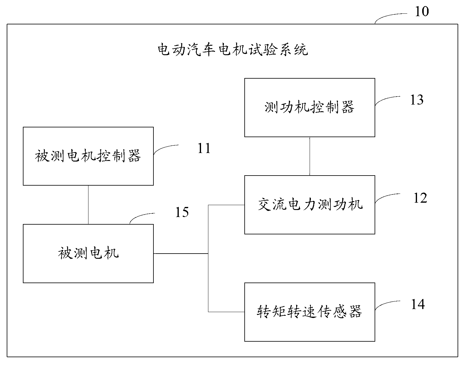
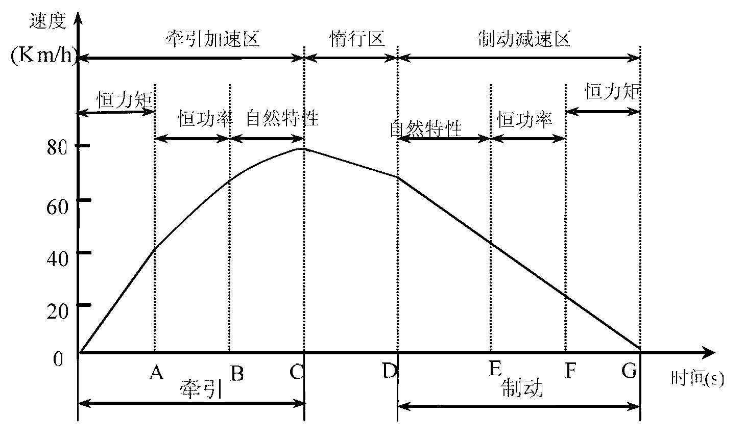
[0006] The invention provides an electric vehicle motor test system, which is used to solve the problem that the motor test system in the prior art cannot satisfy the constant torque below the rated speed point of the electric vehicle motor, and the constant power load above the rated speed point

Method used


Image

  • Motor test system and control method for electric vehicle
  • Motor test system and control method for electric vehicle
  • Motor test system and control method for electric vehicle

Examples


Embodiment 2

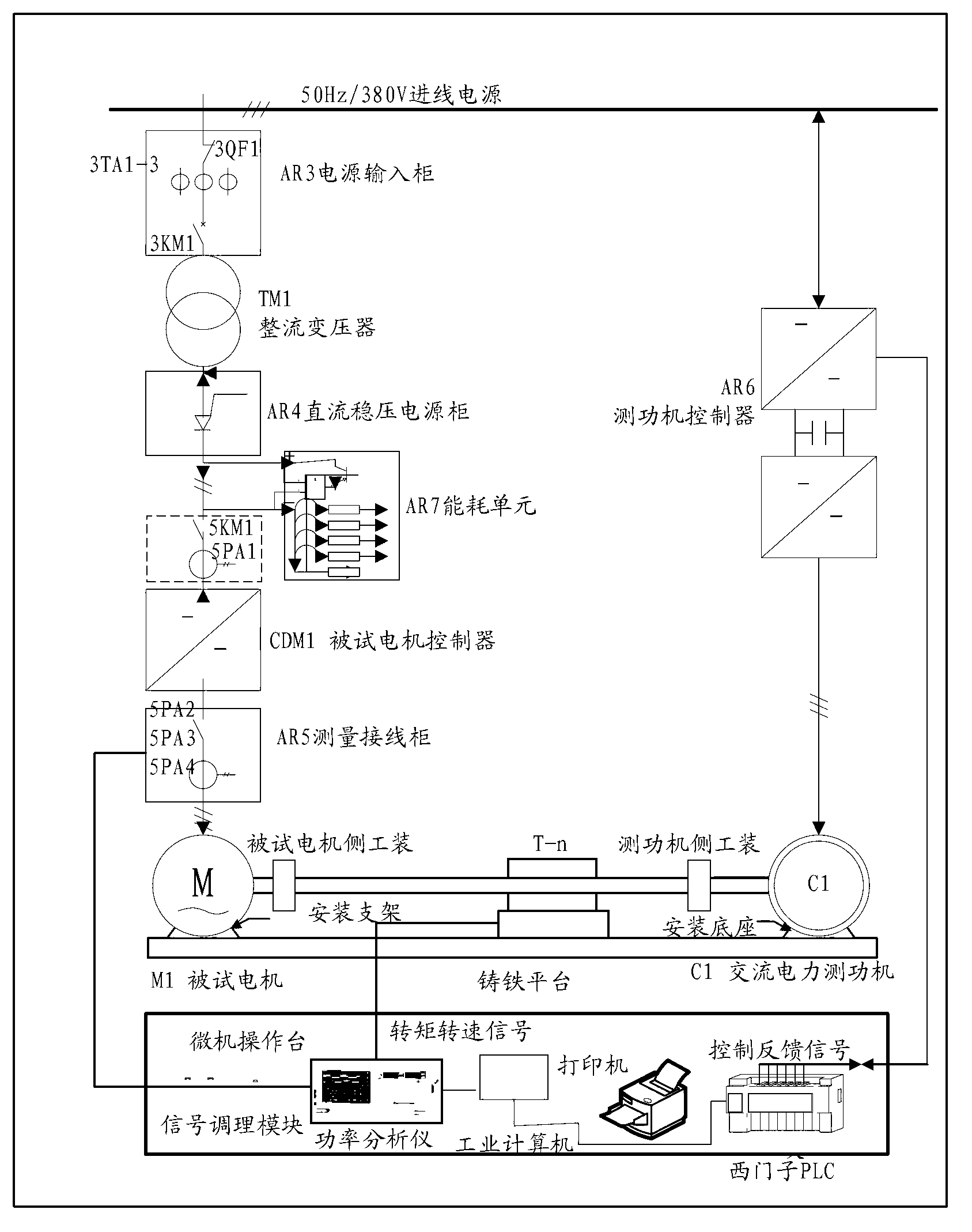
[0039] The difference between the electric vehicle motor test system of this embodiment and the electric vehicle motor test system in the above-mentioned embodiment 1 is that the system of this embodiment also includes a rectifier power supply with a feeder and an energy consumption unit, due to the addition of these two components, the system of this embodiment can realize the feed test of electric vehicle motor. Moreover, this embodiment describes other components included in the electric vehicle motor test system in addition to the components included in Embodiment 1.

[0040] image 3 It is a structural block diagram of an electric vehicle motor test system according to Embodiment 2 of the present invention.

[0041] Such as image 3 As shown, the test system includes the following components:

[0042] The incoming power supply AR3 power input cabinet is equipped with a line protection circuit breaker and a breaking contactor. The incoming power supply cabinet is used for...

Embodiment 3

[0047] Figure 4 It is a flow chart of the electric vehicle motor test control method according to Embodiment 3 of the present invention.

[0048] Such as Figure 4 As shown, the method includes the following steps:

[0049] Step 401: Control the operation of the motor under test to simulate the state of the motor when the electric vehicle is running;

[0050] Step 402: Control the AC power dynamometer to provide resistance for the motor under test according to the running state of the motor under test;

[0051] Step 403: Detect the speed value, torque value, and response time value corresponding to each running state of the motor under test.

[0052] The electric vehicle motor test control method in this embodiment is mainly used to control the various equipment of the electric vehicle motor test system to realize the traction and electric braking conditions of the electric vehicle. The car is towed, and its output power is transmitted to the AC power dynamometer in the p...


PUM


Abstract

The invention discloses a motor test system for an electric vehicle, and solves the problems that a motor test system in the prior art can not meet neither constant-torque loading when an electric vehicle motor runs below the rated rotational speed nor constant-power loading when the electric vehicle motor runs above the rated rotational speed. The motor test system comprises a tested-motor controller connected with a tested motor and used for controlling the state of the tested motor simulating the operation of the electric vehicle, an AC power dynamometer connected with the output terminal of the shaft of the tested motor and used for providing a load for the tested motor and the controller so as to simulate the required power output during actual operation of the electric vehicle, a dynamometer controller connected with the dynamometer and used for controlling the dynamometer to provide a resisting force for both the tested motor and the tested-motor controller when the tested motor simulates the operation of the electric vehicle, and a rotational speed and torque sensor connected with the output shaft of the tested motor and used for measuring both the rotational speed and the torque of the tested motor. The motor test system can improve the accuracy in testing the electric vehicle motor.

Description

technical field [0001] The invention relates to the field of motor testing for electric vehicles, in particular to an electric vehicle motor testing system and a control method. Background technique [0002] The electric vehicle power drive system requires a wide range of speed regulation, large starting torque, high reserve power, high power density, good reliability, constant torque and constant power range, etc. Considering the capacity of the storage battery, the specific power, specific torque and efficiency of the motor are required to be as high as possible. At the same time, in order to achieve the best match for the performance of the vehicle, the electric motor road vehicle must also meet the performance requirements of the vehicle's power performance, maximum speed, climbing, and full-load acceleration. It can be seen that the motor and controller, which are the power source of the whole system, are the direct factors that determine the performance of electric ve...

Claims


Application Information

Patent Timeline
Patent Type & Authority Applications(China)
IPC IPC(8): G01M15/00G01R31/34G01L3/24
Inventor 李立中黎俊龙永红刘明超夏宇辉易吉良
Owner 株洲中达特科电子科技有限公司
Why Eureka
Eureka Blog
Learn More