Solid waste incinerator without emission of flue gas

A solid waste and incinerator technology, applied in the direction of incinerators, emission prevention, combustion methods, etc., can solve the problems of low thermal efficiency of incinerators, unstable furnace temperature, waste of resources, etc., and achieve significant emission reduction and energy saving effects , The effect of improving thermal efficiency

Inactive Publication Date: 2013-07-10
袁永扬
View PDF12 Cites 0 Cited by
  • Summary
  • Abstract
  • Description
  • Claims
  • Application Information

AI Technical Summary

Problems solved by technology

These incinerators have the following disadvantages: (1) The combustion temperature in the combustion zone in the furnace is in the range of 800-900°C, the combustion temperature is low, the combustion effect is poor, and a large amount of harmful gases such as dioxins will be produced; (2) , During the combustion process, a large amount of flue gas (such as nitrogen oxides, carbon dioxide, sulfur dioxide, and harmful gas dioxins produced by incomplete combustion, etc.) will be emitted to cause secondary pollution; (3), auxiliary fuels (such as (coal, diesel, etc.) will increase the combustion cost, consume a lot of energy, and cause waste of resources; (4), because the combustion aid used in the combustion process of garbage is air, and the nitrogen in the air does not participate in the combustion reaction, and it is To absorb a large amount of heat, resulting in large heat loss and low thermal efficiency
Due to the high cost of flue gas treatment and operation or the lack of maintenance of the flue gas treatment system, etc., a large amount of flue gas contains toxic and harmful gases (such as: sulfur dioxide, carbon monoxide, nitrogen oxides, dioxins, etc.) and fly ash emissions, which are harmful to the environment The air, water and soil cause serious pollution, and the long-term emission of these fumes will endanger the living environment of human beings
[0005] In the existing solid waste incinerator, due to the continuous discharge of a large amount of flue gas, part of the heat of solid waste incineration will be taken away with the flue gas emission, so that the furnace temperature will drop; Low, so it is difficult to burn, and the garbage needs to be dried in advance, which requires a lot of hot air, and part of the heat in the furnace is consumed, which makes the furnace temperature drop; at the same time, due to the large furnace volume of the incinerator, the heat dissipation area of ​​the inner surface of the furnace is large. , The heat dissipation speed is fast and the heat dissipation is large, and part of the heat energy in the furnace is consumed, which makes the furnace temperature drop, resulting in low thermal efficiency of the entire incinerator
[0006] In the existing solid waste incinerators, the combustion accelerants that participate in the combustion and oxidation reactions all use oxygen in the air. Due to the complex composition of solid waste, the difference in calorific value is large, resulting in unstable furnace temperature. When the calorific value of incineration When the temperature is low, fuels with high calorific value such as diesel or coal are generally added to maintain a stable furnace temperature, which consumes part of the energy. When the plastic in solid waste is not fully burned under the condition of an oxidant, a large amount of dioxin, etc. will be produced. Toxic and harmful gases, causing serious environmental pollution
The complete incineration of solid waste usually needs to increase the amount of air entering the furnace to increase the end flow, so that the air and solid waste can form a boiling state in the furnace, but this will lead to an increase in the amount of fly ash in the flue gas , which increases the difficulty of flue gas purification treatment and increases the treatment cost

Method used


Image

  • Solid waste incinerator without emission of flue gas
  • Solid waste incinerator without emission of flue gas
  • Solid waste incinerator without emission of flue gas

Examples


Embodiment Construction

[0024] The present invention is described in further detail by the following examples.

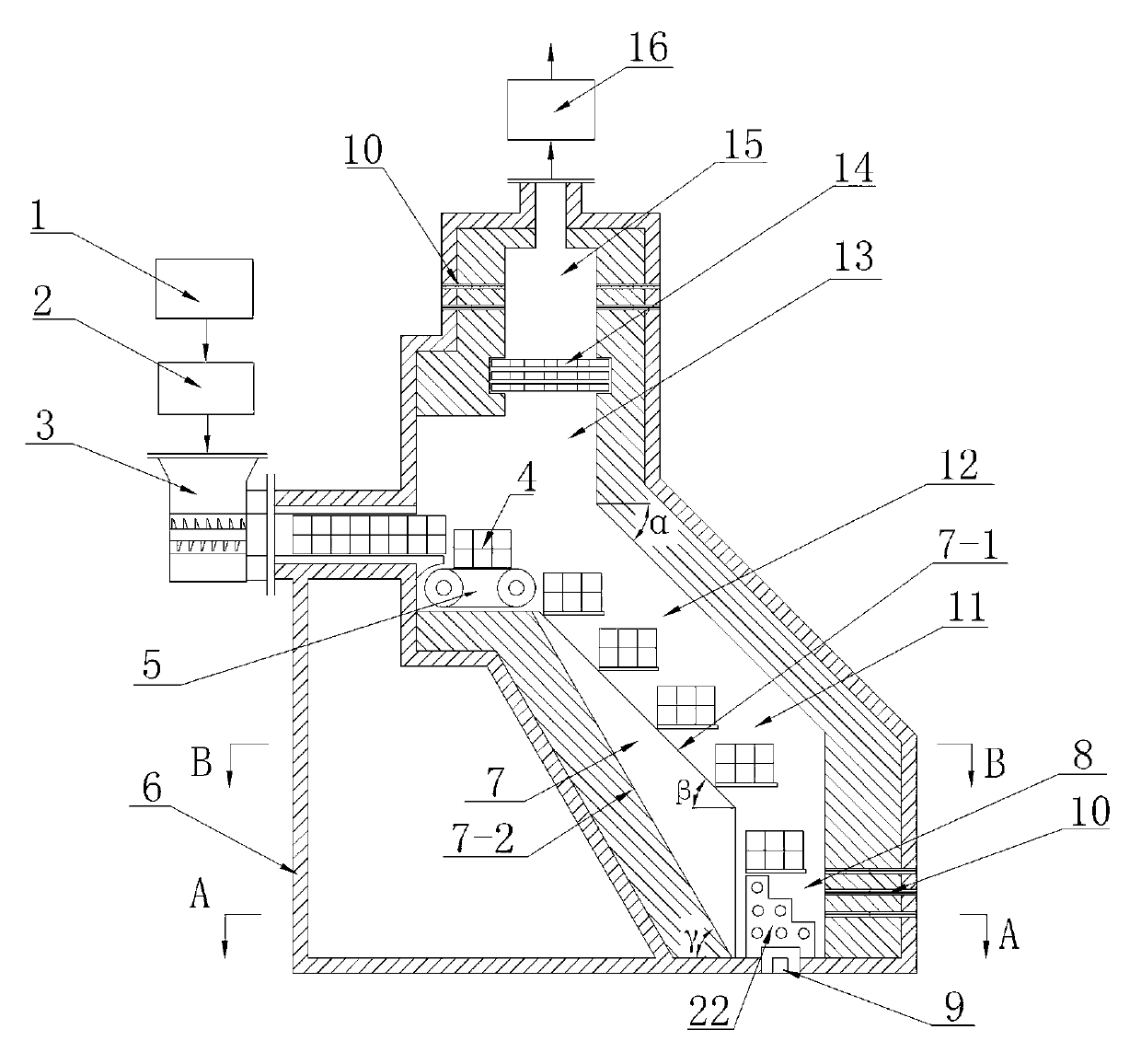
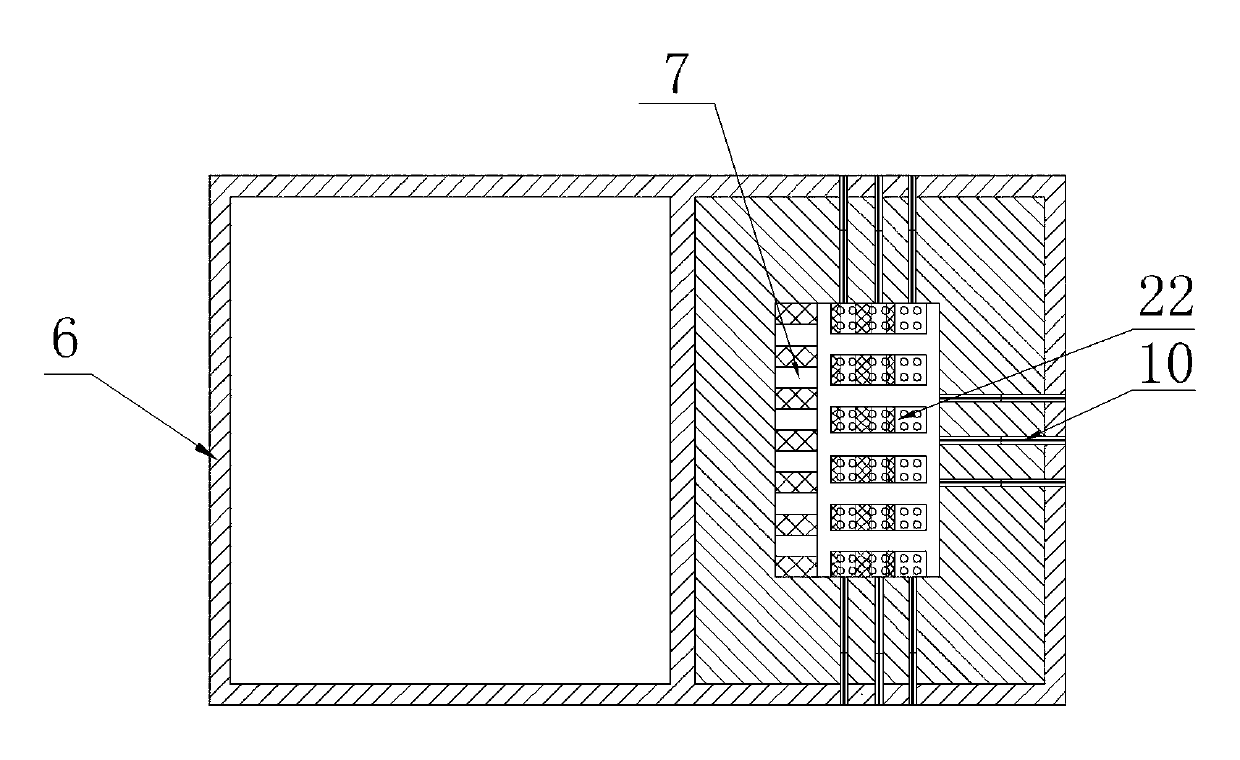
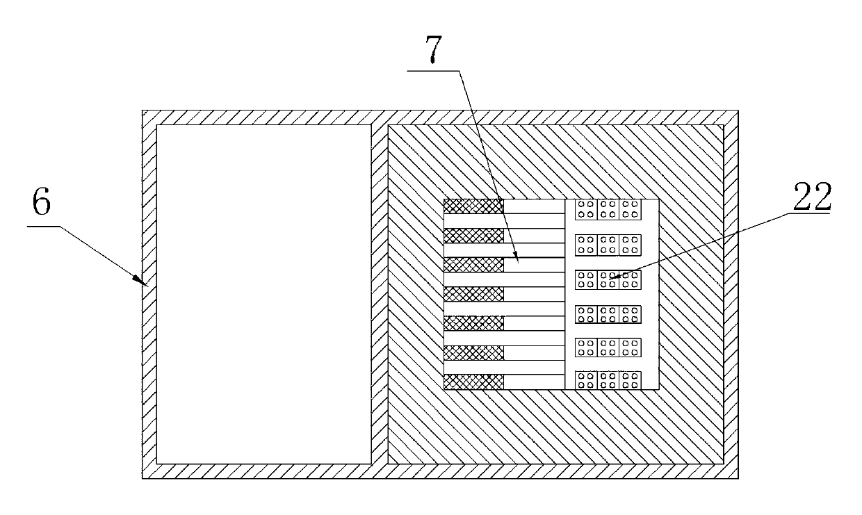
[0025] see figure 1 — Figure 4 As shown, a solid waste incinerator without flue gas emission consists of an incinerator body 6, a vertically structured incinerator hearth 13, a crusher 1, a mixing mixer 2, a compression molding machine 3, and a high temperature resistant belt conveyor 5, boiler furnace 15, induced draft fan 16, heat exchanger 17, desulfurization device 18, purification device 19, carbon dioxide separation device 20, gas mixer 21. The furnace 13 of the incinerator is provided with a drying area 12 , a pyrolysis area 11 and a combustion area 8 sequentially from top to bottom. The bottom of the combustion area 8 is provided with an ash outlet 9 , and the ash outlet 9 is provided with a grid 22 . The cross-section of the incinerator hearth 13 is square, and on the left side of the drying zone 12, the pyrolysis zone 11, and the combustion zone 8 of the incinerator hearth 13,...


PUM


Abstract

The invention discloses a solid waste incinerator without emission of flue gas. An incinerator hearth is in a vertical structure and provided with a drying area, a pyrolysis area and a burning area in sequence from top to bottom; a group of fire pits are arranged at the inner side of the incinerator hearth; three groups of spray guns are respectively arranged at the outer side, the left side and the right side of the burning area; a lump compressed solid waste manufacturing and outputting device is arranged at the outer side of the upper part of the incinerator hearth; the top of the incinerator hearth is provided with a boiler hearth and an induced draft fan; the side wall of the boiler hearth is provided with a group of spray guns; the output end of the induced draft fan is connected with a heat exchanger, a desulphurization device, a purification device, a CO2 separation device and a gas mixer in sequence; and oxygen-enriched gas output by the gas mixer is communicated with the four groups of spray guns. The solid waste incinerator is small in hearth capacity, but large in solid waste dispose amount, high in burning speed, good in effect, available for simultaneously disposing various kinds of solid wastes, energy-saving and environment-friendly; and the solid waste incinerator achieves zero emission of flue gas and does not cause secondary pollution.

Description

technical field [0001] The invention relates to the technical field of solid waste incinerators, in particular to a solid waste incinerator without smoke emission. Background technique [0002] Solid waste includes: urban road cleaning garbage, domestic garbage, catering garbage, medical waste, agricultural product processing waste, feces, waste plastics, tires, organic sludge and hazardous waste such as tanning sludge, electroplating sludge, printing and dyeing sludge etc. The incinerators of existing waste incineration power plants generally burn waste in the range of 800-900 ° C. It is impossible for the incinerators of waste incineration power plants to incinerate waste such as medical waste or sludge, let alone incinerate hazardous waste thing. Medical waste incinerators generally require a furnace temperature of 1200°C. Existing medical waste incinerators need to add a large amount of fuel to assist combustion, and the operating costs are high, so it is impossible to...

Claims


Application Information

Patent Timeline
Patent Type & Authority Patents(China)
IPC IPC(8): F23G5/027F23G5/14F23G5/46
CPCF23G5/0276F23G5/04F23G5/16F23G5/444F23G5/46F23J15/02F23J2215/10F23J2215/50F23J2219/20Y02E20/34
Inventor 袁永扬
Owner 袁永扬
Why Eureka
Try Eureka