Vertical low-carbon and energy-saving counter burning furnace

A back-burning furnace and vertical technology, which is applied in the field of vertical low-carbon and energy-saving back-burning furnaces, can solve the problems of limited use range, low thermal efficiency, no heat exchange function, etc. The effect of increasing the coefficient and increasing the number of air distribution

Inactive Publication Date: 2012-10-03
卢瑞琳
View PDF3 Cites 9 Cited by
  • Summary
  • Abstract
  • Description
  • Claims
  • Application Information

AI Technical Summary

Problems solved by technology

[0004] Most of the existing boilers or heating furnaces adopt the natural combustion method in which fuel is added to the bottom and pyrotechnics go upwards. Most of the heat exchange fire tubes or water tubes are horizontal or vertical round tubes, which have the advantages of small smoke exhaust resistance and simple structure. , small footprint, low product cost, and easy to popularize and use. The disadvantage is that most of the heat energy escapes quickly from the chimney at the top. Some furnace bases are made of red bricks, cement, and sand, which are easily damaged. They have to be dismantled and rebuilt every two or three years, which is a waste of labor. Some furnace bases are made of steel, both of which have single functions and no heat exchange function. The loss is large, and the lower part of the fire carbon is easy to extinguish waste due to fire ash burial and unreasonable air distribution. Some users have to shovel out the high-temperature carbon fire in order to prevent the burnout of the grate. The reason is that the flame is often covered, so that the firepower fluctuates, leading to insufficient combustion, waste of fuel, more black smoke, and serious pollution of the environment, and its tube area is more dusty, the heating surface is small, the thermal efficiency is low, and the temperature rises slowly. With the development of economy and society, the environmental requirements are becoming stricter and the energy price is rising rapidly. In recent years, it has been difficult to meet the needs of energy conservation and environmental protection in production and life. The advantages of horizontal furnaces are their advanced technology, high Large area, high consumption of steel, high heat loss of the equipment body, high price, and limited application range, usually only used in large and medium-sized energy-consuming places; ordinary vertical reverse burning furnace adopts the negative pressure that the upper part is fueled and pyrotechnics move downward The combustion method combines some of the advantages of the above two, but its disadvantages are that the furnace mouth cannot be too high, there are few heat exchange tubes, the heat exchange area is limited, and the tube area is a lot of dust, and the grate is easy to burn and difficult to replace; Existing stove technology usually can only be equipped with primary air and secondary air. With secondary air, the fuel can be burned more fully than natural combustion. Although the tertiary air distribution can add oxygen, but because there is not enough fire to ignite again, the cold wind will instead Lowering the temperature of the furnace is generally not used, so it is difficult to achieve the effect of complete combustion; these types of furnace water exchange pipes are more prone to fouling, and need to be cleaned with acid or alkali boiling furnaces, causing secondary pollution. The current smoke and dust control technology usually adopts gravity sedimentation dust removal (such as smoke cabinet), centrifugal dust removal (such as cyclone dust collector), water bath dust removal (such as water film dust collector or Venturi dust collector), etc. Auxiliary equipment or facilities consume materials, and the better the dust removal effect, the higher the operating cost of the equipment. Although the water bath type has better effect, it consumes a lot of water and electricity, and it pollutes the water source very seriously.

Method used


Image

  • Vertical low-carbon and energy-saving counter burning furnace
  • Vertical low-carbon and energy-saving counter burning furnace
  • Vertical low-carbon and energy-saving counter burning furnace

Examples


Embodiment Construction

[0028] The present invention will be further described below in conjunction with the accompanying drawings in the specification:

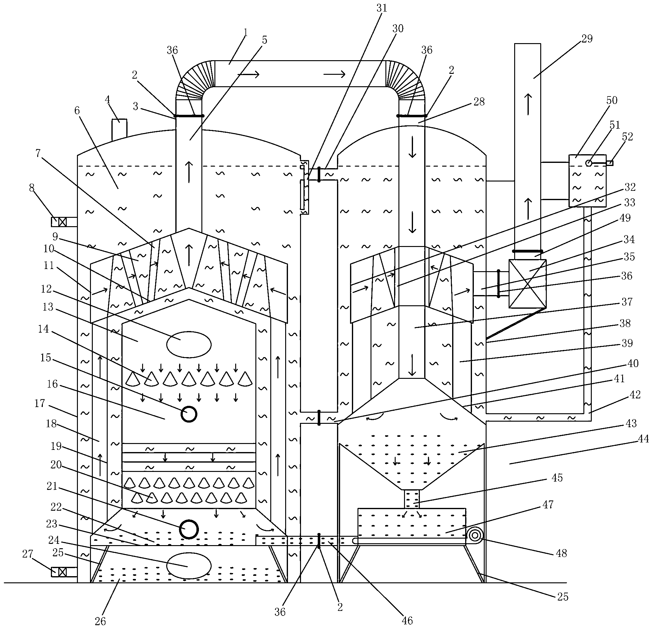
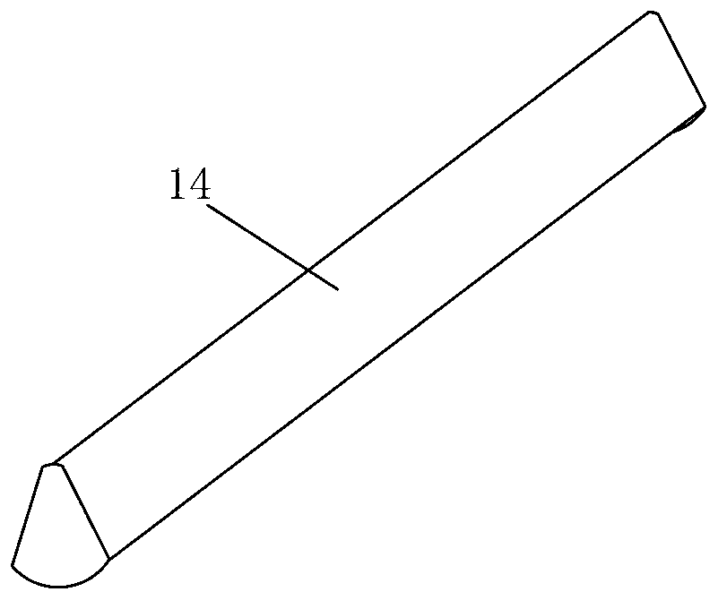
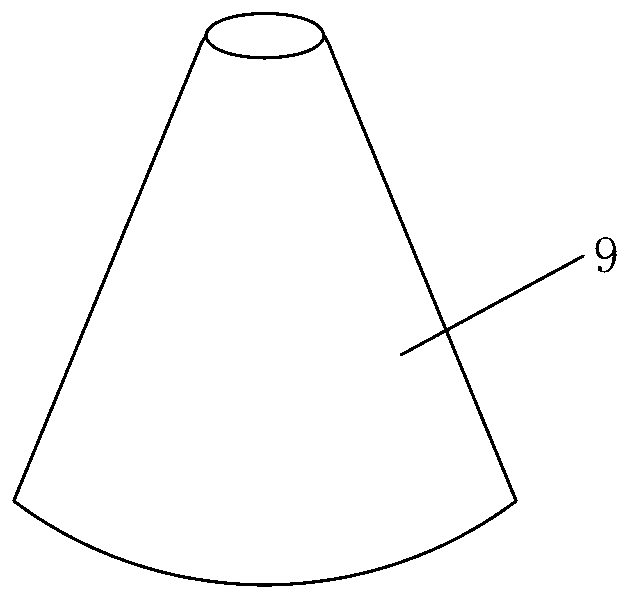
[0029] As attached figure 1 , Attached figure 2 , Attached image 3 As shown, the present invention discloses a vertical low-carbon energy-saving counter-burning furnace, including a vertical cross-section arranged in the middle and lower part of the counter-burning furnace body 17 in a "convex" shape. There is a larger horizontal furnace liner 11, and the two furnace lines are connected by a plurality of straight fire tubes 18 surrounding the middle and upper part of the vertical anti-burning furnace liner 19, and a waste heat flue is provided on the top of the horizontal furnace liner 11. 5. The lower end of the waste heat flue 5 is connected to the horizontal furnace liner 11, and the top of the upper part passing through the back burner body is the waste heat flue outlet 3, and a soot back-burning waste heat exchanger 44 is provided on one side o...


PUM


Abstract

The invention discloses a vertical low-carbon and energy-saving counter burning furnace, which comprises a vertical counter burning furnace pipe and a large horizontal furnace pipe. The vertical counter burning furnace pipe is arranged on the middle lower part in a counter burning furnace body, the vertical section of the vertical counter burning furnace pipe is inverted-'T'-shaped, the large horizontal furnace pipe is arranged on the middle upper part in the counter burning furnace body, the two furnace pipes are communicated with each other by a plurality of straight fire tubes surrounding the upper part of the vertical counter burning furnace pipe, a flue is arranged on the top of the horizontal furnace pipe and penetrates through the top of the counter burning furnace body to form an afterheat flue outlet, a smoke back-combustion type afterheat apparatus is arranged on one side of the counter burning furnace body and consists of a body and a container, an afterheat flue inlet is formed in the top of the smoke back-combustion type afterheat apparatus and is communicated with the afterheat flue outlet via a flue connecting tube, inverted-fan-shaped water tubes are transversely placed in the vertical counter burning furnace pipe, and horn-shaped water tubes are vertically placed in the horizontal furnace pipe. The invention has the advantages that vertical low-carbon and energy-saving counter burning furnace is compact in structure, high in thermal efficiency, stable in performance and easy to popularize and use, and gasification and combustion are performed directly, the height of the furnace body is selectable, secondary pollution is avoided during dust removal, smoke discharge meets requirements on environment friendliness, and the like.

Description

Technical field [0001] The invention relates to the technical field of heating, in particular to a vertical low-carbon energy-saving back-burning furnace. Background technique [0002] Low carbon, English as low carbon, means lower (lower) greenhouse gas (carbon dioxide-based) emissions. With the development of the world’s industrial economy, the rapid increase in population, the unlimited rise of human desires and the unrestrained production and lifestyles, the world’s climate is facing more and more serious problems, carbon dioxide emissions are increasing, and the earth’s ozone layer is suffering unprecedented Crisis, global catastrophic climate change has repeatedly appeared, which has seriously endangered the living environment and health and safety of mankind. Even the high-speed growth or swelling GDP that mankind was once proud of was greatly discounted due to environmental pollution and climate change (for this reason, countries have called for the development model and...

Claims


Application Information

Patent Timeline
Patent Type & Authority Applications(China)
IPC IPC(8): F22B1/00F22B31/08F23B80/00F23J15/06
CPCY02E20/30
Inventor 卢瑞琳
Owner 卢瑞琳
Why Eureka
Try Eureka