
Machining tooling fixture for welding joint tensile sample and clamping and positioning method for machining tooling fixture

A technology for fixtures and tensile samples, applied in positioning devices, manufacturing tools, metal processing equipment, etc., can solve the problem of not meeting the processing requirements of welded joint tensile samples, affecting the manufacturing progress, and poor verticality of samples, etc. problems, to achieve the effect of improving machining efficiency, reducing processing costs, and positioning reasonably

Active Publication Date: 2012-10-03
SHANGHAI ELECTRIC NUCLEAR POWER EQUIP CO LTD
View PDF5 Cites 11 Cited by
  • Summary
  • Abstract
  • Description
  • Claims
  • Application Information

AI Technical Summary

Problems solved by technology

[0003] At present, in the commonly used processing methods, the other two sides of the sample are mainly clamped by flat pliers on the milling machine to realize positioning processing, but the verticality of the processed sample is poor, and the processing efficiency is low, which affects the manufacturing process. production progress
At the same time, the thickness of most test plates for joint stretching exceeds 10mm, and the wear and tear on the milling cutter during each processing is very serious. The thicker the sample thickness is, the more serious the situation is. It can be seen that, no matter from a technical or economic point of view, Such processing methods cannot meet the processing requirements of welded joint tensile specimens

Method used


Image

  • Machining tooling fixture for welding joint tensile sample and clamping and positioning method for machining tooling fixture
  • Machining tooling fixture for welding joint tensile sample and clamping and positioning method for machining tooling fixture
  • Machining tooling fixture for welding joint tensile sample and clamping and positioning method for machining tooling fixture

Examples


Embodiment Construction

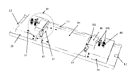
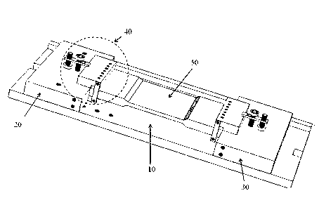
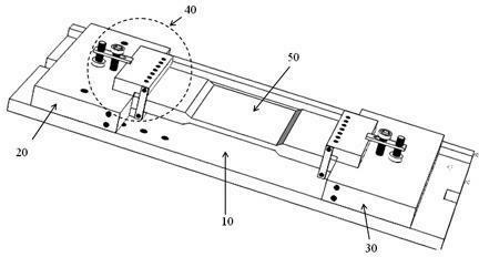
[0035] The present invention provides a machining tooling fixture (hereinafter also referred to as a tooling fixture) for positioning a welded joint tensile specimen (hereinafter also referred to as a tensile specimen, or specimen) during processing. Combine figure 1 , figure 2 The following will mainly describe a specific implementation structure when the above tooling fixture is used to position a plate-shaped sample.

[0036] See also figure 1 , figure 2 As shown, the tooling fixture of the present invention mainly includes: a base 10, a movable support block 20, a fixed support block 30, and two clamping parts 40 of the sample clamping device. The "length direction" of each part in the text refers to the direction that is consistent with the length of the clamp; for any two parts in the clamp that are arranged opposite to each other, "inside" refers to the side close to each other, "outside" It is the side away from each other.

[0037] A number of positioning grooves 12 a...


PUM


Abstract

The invention relates to a machining tooling clamp for a welding joint tensile sample and a clamping and positioning method for the welding joint tensile sample. A base is mounted on a milling machine. A sample to be machined is fixedly arranged between a fixed support block and a movable support block which are arranged in opposite positions on the base through two clamping parts of a sample clamping device; the space between the movable support block and the fixed support block can be changed by adjusting the position of the movable support block on the base so as to adapt to the length of the sample; after one surface of the sample is machined, the sample clamping device and the sample are taken out and turned and refixed between the movable support block and the fixed support block; and then the other surface of the sample is machined. Therefore, according to the machining tooling fixture and the clamping and positioning method disclosed by the invention, the machining work efficiency can be increased, the machining precision is ensured and the machining cost is greatly reduced simultaneously.

Description

Technical field [0001] The invention relates to the field of tooling, in particular to a tooling fixture for processing welded joint tensile samples and a clamping and positioning method thereof. Background technique [0002] When nuclear power manufacturers conduct tests on welding materials, welding process qualification, product witness parts, etc., tensile strength is used as an evaluation index, and this evaluation index is indispensable. Generally, it is necessary to perform high-precision processing on two sides of the gauge length of the plate-shaped tensile specimen (or arc-shaped tensile specimen), and the processing accuracy will directly affect the correctness and reliability of the tensile test data. [0003] At present, the commonly used processing methods mainly use flat-nose pliers to clamp the other two sides of the sample on the milling machine to achieve positioning processing. The processed sample has poor verticality and low processing efficiency, which affects...

Claims


Application Information

Patent Timeline
Patent Type & Authority Applications(China)
IPC IPC(8): B23Q3/06
Inventor 赵炜林仁军陆连萍李晓冬
Owner SHANGHAI ELECTRIC NUCLEAR POWER EQUIP CO LTD
Learn More