
Light guide plate, manufacturing method thereof, and side-entry backlight module using the light guide plate

A manufacturing method and technology for a light guide plate, applied in the field of backlight modules, can solve the problems of bending, poor optical isolation effect, low yield, etc., and achieve the effect of high optical isolation effect, high optical isolation degree, and quantitative production.

Inactive Publication Date: 2016-07-06
TCL CHINA STAR OPTOELECTRONICS TECH CO LTD
View PDF8 Cites 0 Cited by
  • Summary
  • Abstract
  • Description
  • Claims
  • Application Information

AI Technical Summary

Problems solved by technology

In the traditional side-illuminated backlight module, the diffusion of light by the light guide plate makes the effects of localdimming, scanning3D, dynamic contrast improvement and power saving not good.
In order to overcome the above shortcomings, the light guide plate is designed as a light guide plate with a microstructure. However, the existing light guide plate with a microstructure has poor light isolation effect, low yield, poor mass production, and severe deformation after absorbing moisture. defects, and its cost is more than 25% higher than ordinary light guide plates

Method used


Image

  • Light guide plate, manufacturing method thereof, and side-entry backlight module using the light guide plate
  • Light guide plate, manufacturing method thereof, and side-entry backlight module using the light guide plate
  • Light guide plate, manufacturing method thereof, and side-entry backlight module using the light guide plate

Examples


Embodiment Construction

[0039] In order to further illustrate the technical means adopted by the present invention and its effects, the following describes in detail in conjunction with preferred embodiments of the present invention and accompanying drawings.

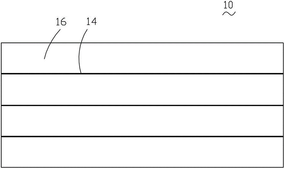
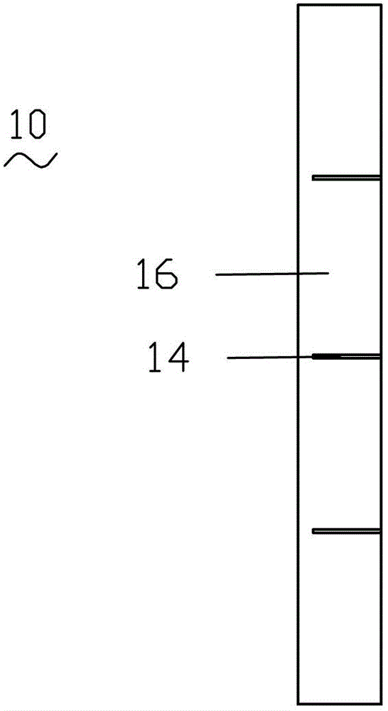
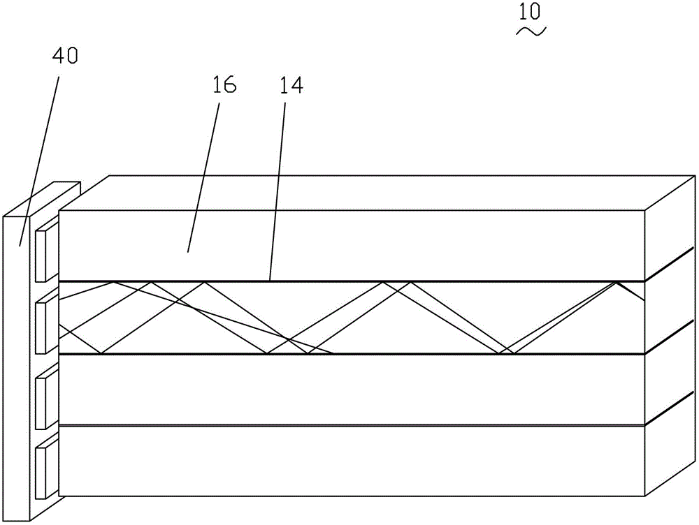
[0040] see Figures 1 to 3 , the present invention provides a light guide plate 10 on which several reflective partition walls 14 are arranged, and the light guide plate 10 is divided into several partitions 16 by the reflective partition walls 14 . The number of reflective partition walls 14 is set accordingly according to the number of required partitions 16 .

[0041] The width of the reflective partition wall 14 is smaller than the thickness of the light guide plate 10 . The reflective partition wall 14 is in the shape of a sheet, and its surface is a mirror surface. The reflective partition wall 14 is a metal sheet, and the thickness of the metal sheet is 0.2 mm to 1 mm. In this embodiment, the surface of the metal sheet is polished to...


PUM


Abstract

A light guide plate (10) and a producing method thereof, and a side backlight module applying the light guide plate (10). The light guide plate (10) is disposed with multiple reflection isolation walls (14), the reflection isolation walls (14) divide the light guide plate (10) into several sub-sections (16), and surfaces of the reflection isolation walls (14) are mirror surfaces. In the light guide plate (10), the reflection isolation walls (14) are set between individual sub-sections (16), so that light emitting from one individual sub-section (16) to the reflection isolation walls (14) is reflected back to the individual sub-section (16), and is limited within the individual sub-section (16), thereby implementing luminance section division of the light guide plate (10) and independent control of area luminance, and having a greater light isolation effect. Through this method, the light guide plate (10) having the reflection isolation walls (14) can be produced, the method is simple and convenient, has good yield, can provide measurable production, and has low costs. The side backlight module applies the light guide plate (10), thereby implementing luminance section division of the side backlight module and independent control of area luminance, and implementing a high light isolation degree with low costs.

Description

technical field [0001] The invention relates to the field of backlight modules of liquid crystal displays, in particular to the design of light guide plates in side-entry backlight modules. Background technique [0002] A liquid crystal display device (LCD, Liquid Crystal Display) has many advantages such as a thin body, power saving, and no radiation, and has been widely used. Most of the liquid crystal display devices currently on the market are backlight liquid crystal display devices, which include a liquid crystal panel and a backlight module. The working principle of the liquid crystal panel is to place liquid crystal molecules between two parallel glass substrates. There are many vertical and horizontal small wires between the two glass substrates. The direction of the liquid crystal molecules is controlled by electrifying or not, and the light of the backlight module is refracted. Come out to generate the picture. Since the liquid crystal panel itself does not emit...

Claims


Application Information

Patent Timeline
Patent Type & Authority Patents(China)
IPC IPC(8): G02B6/00F21S8/00F21V8/00F21V7/00
CPCG02B6/0055G02B6/0078G02F1/133601
Inventor 黄建发
Owner TCL CHINA STAR OPTOELECTRONICS TECH CO LTD
Learn More