Spinning device with pressing ring capable of adjusting gap

A gap adjustment and spinning wheel technology, which is applied in the field of spinning processing, can solve the problems of tail material instability, prolong production cycle, and low work efficiency, so as to improve material utilization, increase effective forming sections, and optimize contact status effect

Active Publication Date: 2014-11-05
NORTHWESTERN POLYTECHNICAL UNIV
View PDF6 Cites 0 Cited by
  • Summary
  • Abstract
  • Description
  • Claims
  • Application Information

AI Technical Summary

Problems solved by technology

[0004] At present, in the prior art, in addition to reserving a certain machining allowance at the tail end of the blank and processing it with a machine after spinning, the processing method for the bell mouth produced at the end of the forward spinning of the cylindrical part is In addition to the cutting method, there is also a multi-pass shrinking spinning process to shrink and eliminate the bell mouth at the end of the workpiece after the spinning is completed, but this multi-pass shrinking process will greatly extend the production cycle. Low working efficiency, and when shrinking the bell mouth at the tail end of the workpiece, the material at the tail end is prone to instability, and in severe cases, it will wrinkle or break
In summary, the existing technology has not yet proposed a method that can effectively and specifically suppress the positive spinning of the tail end of the cylindrical part.

Method used


Image

  • Spinning device with pressing ring capable of adjusting gap
  • Spinning device with pressing ring capable of adjusting gap
  • Spinning device with pressing ring capable of adjusting gap

Examples


Embodiment Construction

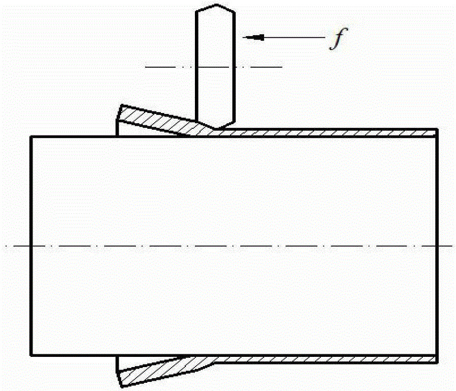
[0030] This implementation case is a device and method for suppressing the forward spinning of the bell mouth at the tail end of an aluminum alloy cylindrical part. The blank of the cylindrical part is an LF21M aluminum alloy pipe with an outer diameter of 265 mm, an inner diameter of 253 mm, a pipe wall thickness of 6 mm, and an axial length of 1000 mm. In the spinning process of this implementation case, the thickness reduction of the blank is 2 mm.

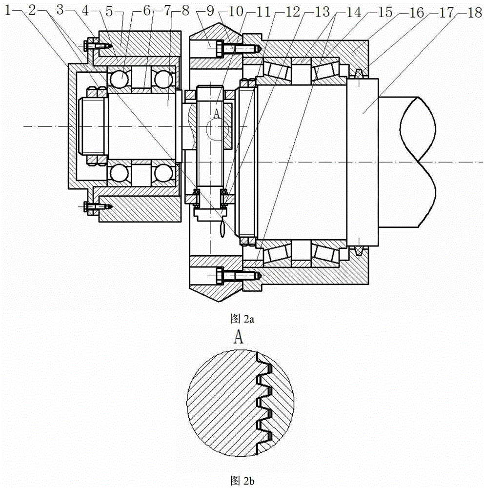
[0031] This embodiment includes a rotary wheel mandrel 18, a rotating body 16, a rotary wheel 9, a roller bearing 15, a bearing positioning sleeve 14, a screw pair, a pressure ring shaft 8, a pressure ring 5, a fixed sleeve 4, an angular contact bearing 6, a sleeve barrel 7 and bearing cover 1, and:

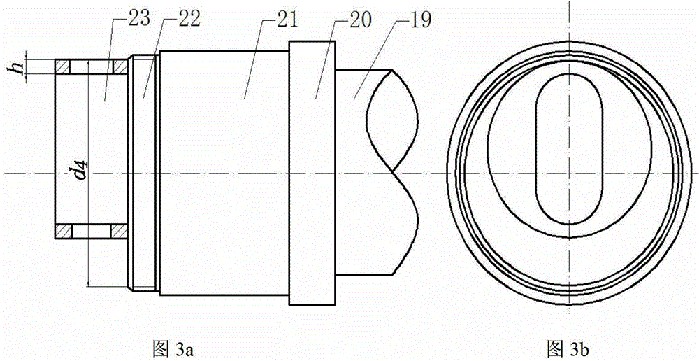
[0032] The rotary wheel mandrel 18 is a five-stage stepped shaft, which are respectively: the first stage shaft 19 of the rotary wheel mandrel for installing the rotary wheel seat feed mechanism, and the rotary wheel core for ins...


PUM

PropertyMeasurementUnit
lengthaaaaaaaaaa
widthaaaaaaaaaa
depthaaaaaaaaaa

Abstract

A spinning device with a pressing ring capable of adjusting a gap, comprises a rotating body, 2 locking nuts and a spinning roller installed on a spinning roller core shaft. A first level shaft is securely fitted to a shaft hole of a feeding mechanism of a spinning roller base. A fifth level shaft of the spinning roller core shaft is an eccentric shaft, and eccentric distance from an axis of the fifth level shaft to an axis of a fourth level shaft is 1 / 8d4. An end surface of the fifth level shaft of the spinning roller core shaft is provided with a sliding groove used for the slide of a first level shaft of a pressing ring shaft. The pressing ring shaft is arranged on a shaft end surface of the spinning roller core shaft, and is inserted into the sliding groove of the end surface of the fifth level shaft of the spinning roller core shaft, the position of the pressing ring shaft in the sliding groove of the spinning roller core shaft being adjusted through a screw in a screw pair. The pressing ring provided in the invention can generate inward radial extrusion effect on raised blank in the front of the spinning roller in a spinning process, so as to limit outward radial flow of the material in the front of the spinning roller, promote axial flow of the material in a processing process, inhibit expanding of the bank in a non-spinning area, and finally to prevent formation of a horn mouth shape at the end of the blank in the last spinning period, thereby increasing effective forming section of a spinned part, and improving utilization rate of the material.

Description

technical field [0001] The invention belongs to the field of spinning processing, in particular to a device for preventing a cylindrical part from forward spinning a bell mouth at a tail end. Background technique [0002] Forward spinning of cylindrical parts is a continuous local plastic forming method for forming high-precision thin-walled cylindrical parts. It has the characteristics of small spinning force, high production efficiency and low labor intensity. In the forward spinning process of cylindrical parts, one end of the cylindrical blank is fixed to the mandrel by the clamping device and the axis of the cylindrical blank coincides with the axis of the mandrel, and the active rotation of the mandrel drives the synchronous rotation of the billet and the mandrel. The rotary wheel makes a linear feed motion to the other end of the cylindrical blank along the axial direction of the mandrel, so that the thickness of the cylindrical blank is reduced and the length is elon...

Claims


Application Information

Patent Timeline
Patent Type & Authority Patents(China)
IPC IPC(8): B21D22/16
Inventor 詹梅石丰王巧玲杨合
Owner NORTHWESTERN POLYTECHNICAL UNIV
Why Eureka
Try Eureka