Spraying axial-current fan with ring-shaped water-jet pipe

A technology of annular water spraying and axial flow fans, which is applied in household appliances, mechanical equipment, machines/engines, etc. It can solve the problems of strong impact on water droplets by blades, narrow range of working conditions, and damage to blades, so as to reduce the energy of moving blades. consumption, safety improvement, and tip wear reduction

Inactive Publication Date: 2010-07-21
XI AN JIAOTONG UNIV
View PDF5 Cites 2 Cited by
  • Summary
  • Abstract
  • Description
  • Claims
  • Application Information

AI Technical Summary

Problems solved by technology

During the long-term operation of the spray fan, due to the difficulty of monitoring, the fan will mistakenly enter into the working condition of high water-air ratio, and the motor will often be burned due to the large increase in power
Secondly, when the spray fan is running for a long time, there is still a situation where the blade hits water droplets too hard, causing the blade to be damaged.
[0005] Although the appearance of the existing spray axial flow fan has greatly reduced the power consumption of the old air conditioning system, as the key equipment of the new textile air conditioning system, it has high energy consumption, low efficiency, narrow range of working conditions, and hidden dangers of safe operation. , the design and development of a new type of energy-saving spray axial flow fan that can adapt to the working condition of large water-air ratio has strong practical significance

Method used


Image

  • Spraying axial-current fan with ring-shaped water-jet pipe
  • Spraying axial-current fan with ring-shaped water-jet pipe
  • Spraying axial-current fan with ring-shaped water-jet pipe

Examples


Embodiment Construction

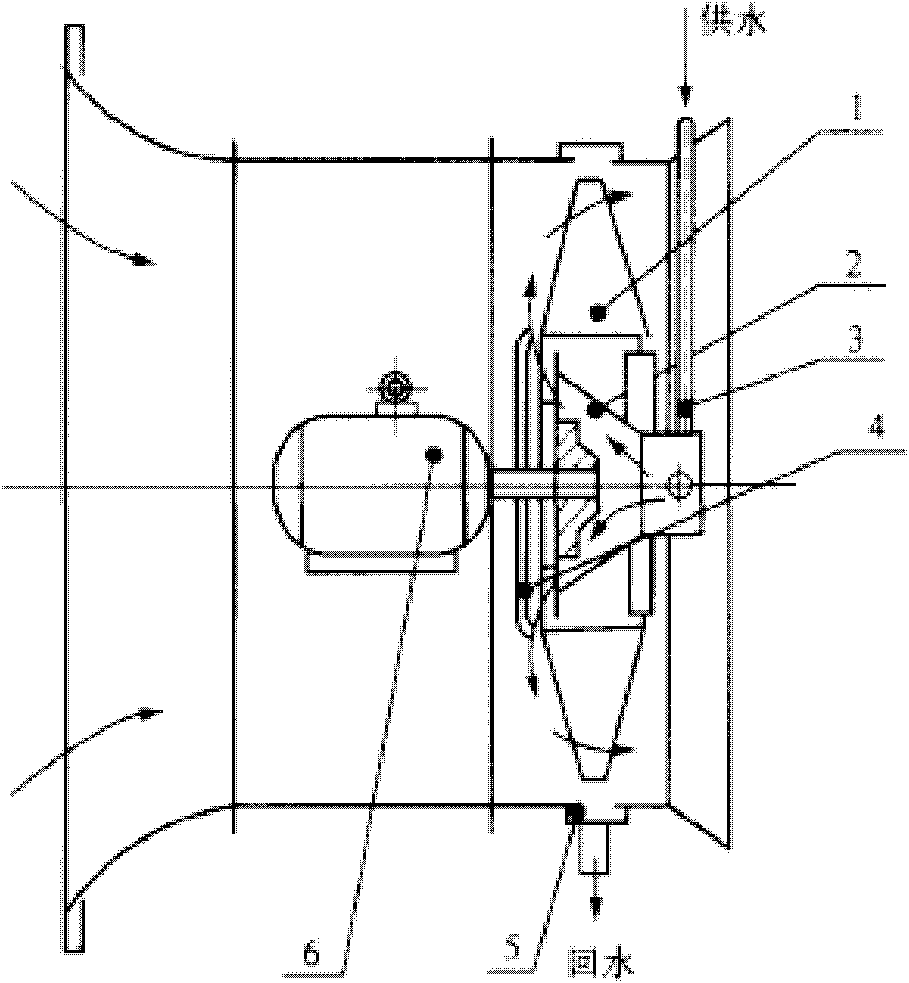
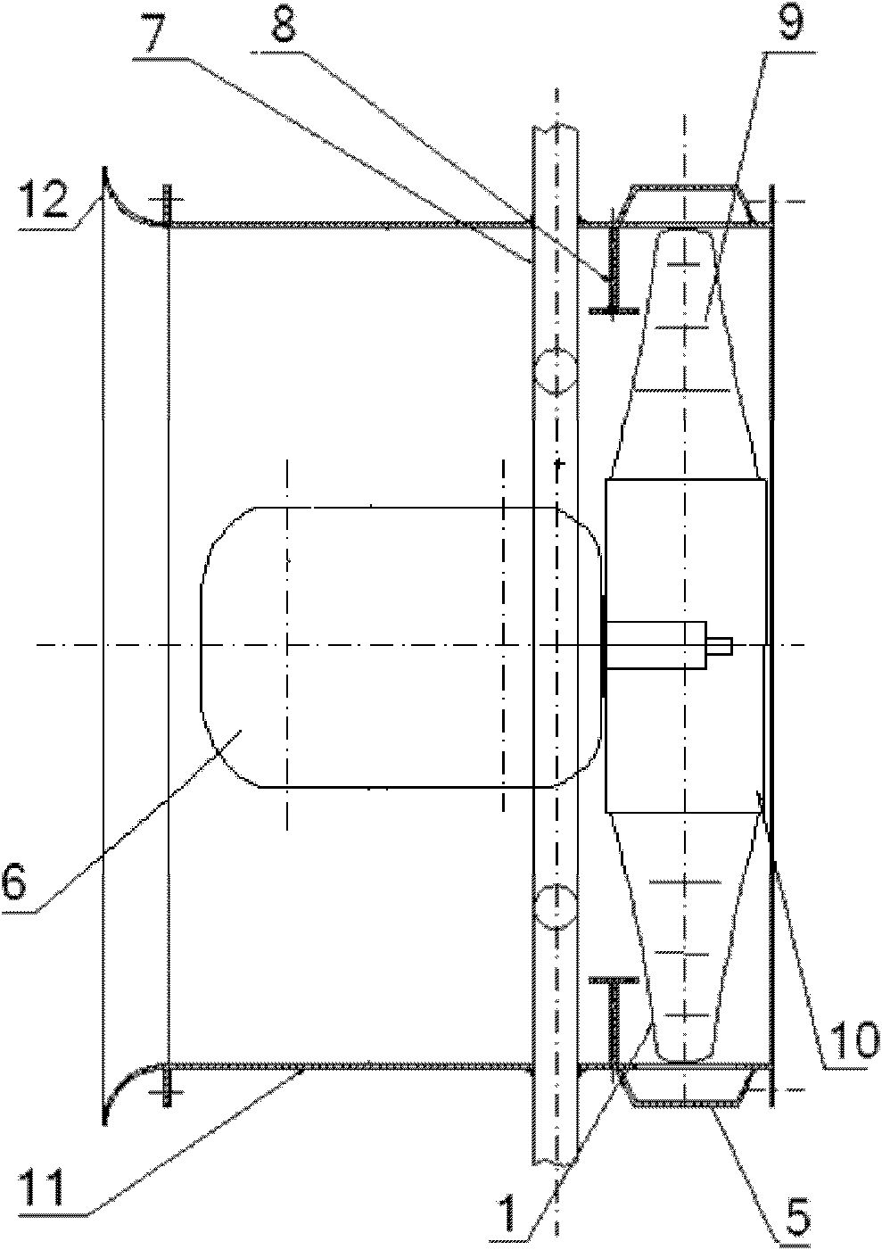
[0016] see figure 2 , a spraying axial flow fan with an annular water spray pipe, comprising a collector 12, a fan cylinder 11, a motor 6, a wheel hub 10, moving blade blades 1 and a drainage grid 5, between the motor 6 and the wheel hub 10, set There are annular water spray pipes 7 and radial water retaining rings 8, and additional guide vanes 9 are arranged on the rotor blades 1.

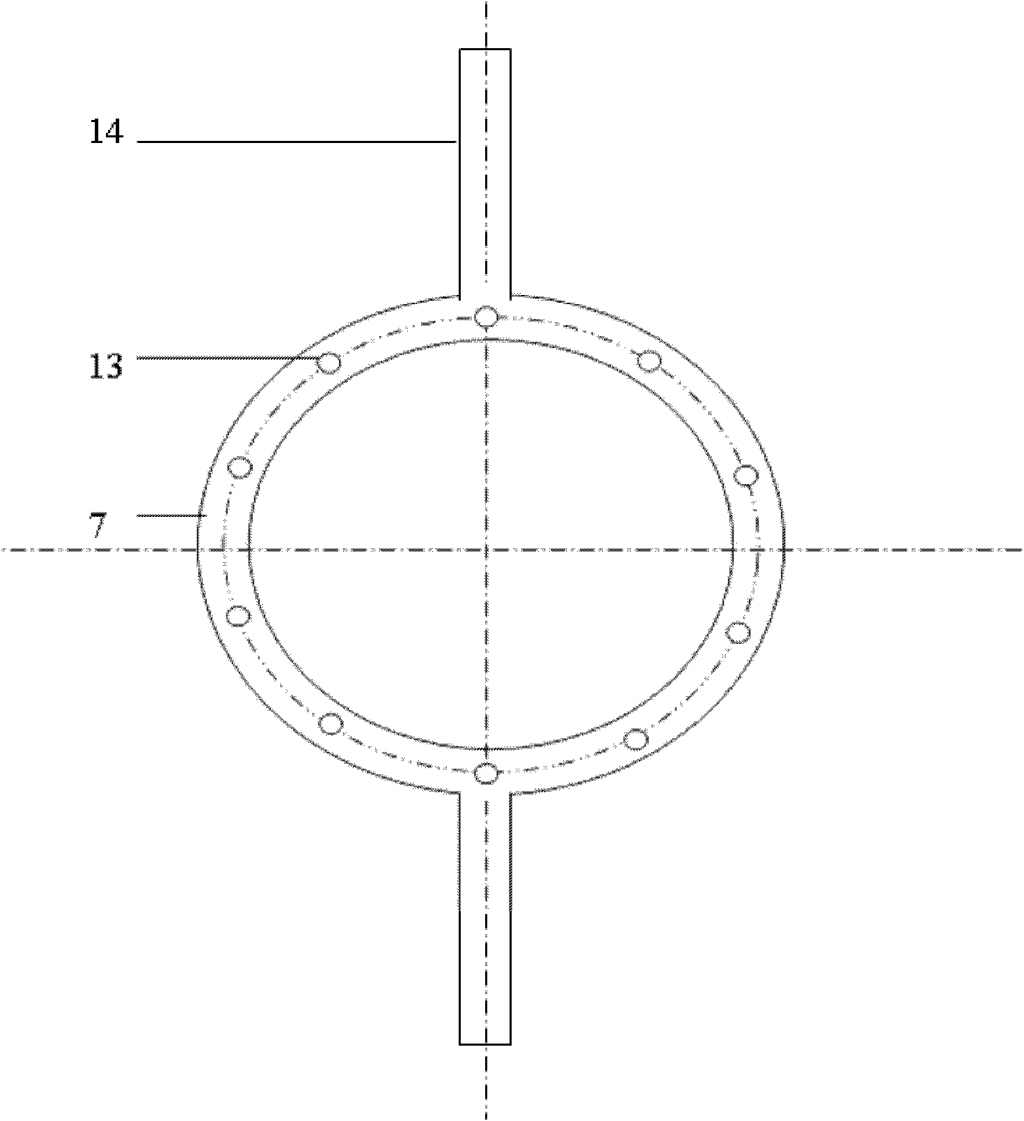
[0017] see image 3 , the above-mentioned annular water spray pipe 7 is passed into the water flow through the water delivery pipe 14, and the side of the water spray pipe facing the rotor blade 1 is provided with 6 to 10 circumferentially evenly distributed circular or other shaped (such as elliptical) small water spray pipes. Hole 13, a small section of pipe can also be connected to control the water spraying direction on the water spraying hole, and water is sprayed to the rotor blade 1 of rotation with approximate axial direction.

[0018] The radial water retaining ring 8 is arranged at th...


PUM


Abstract

The invention discloses a spraying axial-current fan with a ring-shaped water-jet pipe. The fan comprises a fan drum, an inlet of the fan drum is provided with a current-collector, a drainage gate is arranged close to the fan drum, a motor is arranged in the fan drum, and an output shaft of the motor is connected with a wheel hub provided with moving blades. The fan is characterized in that: the ring-shaped water jet pipe is arranged between the motor and the axial direction of the hub wheel and fixed on the fan drum by a water delivery pipe; the side, facing the moving blades, of the ring-shaped water-jet pipe is provided with water-jet holes uniformly distributed along the circumferential direction; and water current enters the ring-shaped water-jet pipe through the water delivery pipe and then is nearly axially sprayed to rotating moving blades by the water-jet holes. Compared with the conventional spraying axial-current fan, the spraying fan of the invention can work under a condition of bigger water-air ratio, so that the application range of the spraying fan in a spinning air-conditioning room is widened, and simultaneously with the increase of the water-air ratio, the increasing rate of motor power consumption is obviously reduced in relation to the conventional spraying fan, and the decreasing rate of the fan total efficiency is also obviously lowered.

Description

technical field [0001] The invention relates to a spraying axial flow fan, in particular to a spraying axial flow fan with an annular water spray pipe. Background technique [0002] my country is a big textile country. In the spinning process, the temperature and humidity of the workshop play a decisive role in the progress of production and product quality. Therefore, it is necessary to control the air parameters in the workshop and set up air conditioning devices. The widely used textile air-conditioning system is an improved equipment with a spray fan as the core. The existing spray axial flow fan is a new type of fan formed by installing a spray device on the basis of an ordinary axial flow fan. The basic structure is as follows: figure 1 As shown, the water flows from the water inlet pipe into the water jacket of the fan hub, passes through the hub, and then hits the water retaining plate, where it is blocked by the water retaining plate to form a radial centrifugal mo...

Claims


Application Information

Patent Timeline
Patent Type & Authority Applications(China)
IPC IPC(8): F04D25/08F24F6/14
Inventor 席光李景银牛子宁
Owner XI AN JIAOTONG UNIV
Why Eureka
Try Eureka