
Method for detecting carrier phase difference under mismatch delay in transmitter and receiver

A carrier phase difference and transmitter technology, applied in baseband systems, channel estimation, digital transmission systems, etc., can solve the problems of lack of multipoint propagation, meaningless calibration, and high downlink channel information

Active Publication Date: 2012-09-19
王晓安
View PDF2 Cites 4 Cited by
  • Summary
  • Abstract
  • Description
  • Claims
  • Application Information

AI Technical Summary

Problems solved by technology

The calibration process can only compensate for the fixed or slowly changing part of the mismatch in the transmit and receive chain because of its slowness, but it can't do anything for the rapidly changing part
Third, even if the number of calibrations can be made more frequent to track the rapidly changing part of the RF mismatch, since the usual calibration steps require all channel information in the entire signal bandwidth, the feedback overhead will approach or reach that of the FDD network. Feedback overhead, making calibration meaningless
[0007] The benefits of multicast are greatly diminished due to lack of accurate downlink channel information and / or excessive feedback overhead due to the lack of effective and feasible methods to compensate and track mismatches in the transmit and receive chains

Method used


Image

  • Method for detecting carrier phase difference under mismatch delay in transmitter and receiver
  • Method for detecting carrier phase difference under mismatch delay in transmitter and receiver
  • Method for detecting carrier phase difference under mismatch delay in transmitter and receiver

Examples


Embodiment Construction

[0021] In order to understand the technical content of the present invention more clearly, the following examples are given in detail.

[0022] The present invention describes the inventive subject matter disclosed in the present application with the aid of the drawings. Numerical designations referred to in the description correspond to corresponding elements in the drawings. The following describes several specific details for purposes of explanation in order to achieve a detailed understanding of the subject matter of the invention. In many instances, however, these specific details may not be necessary to put the inventive subject matter into practice.

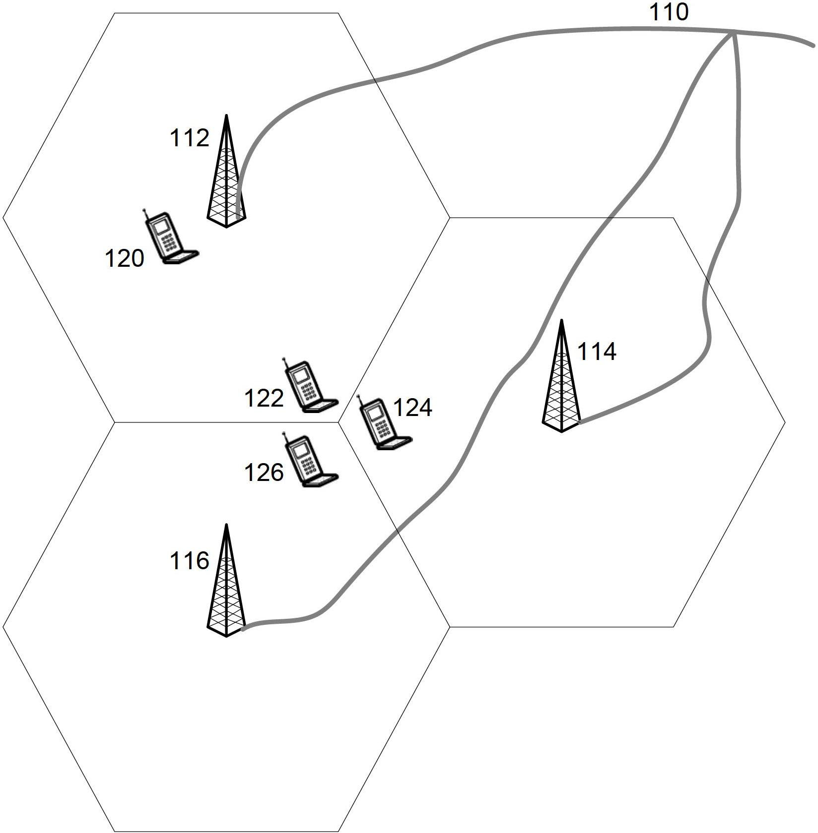
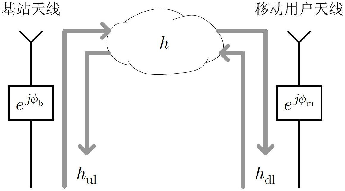
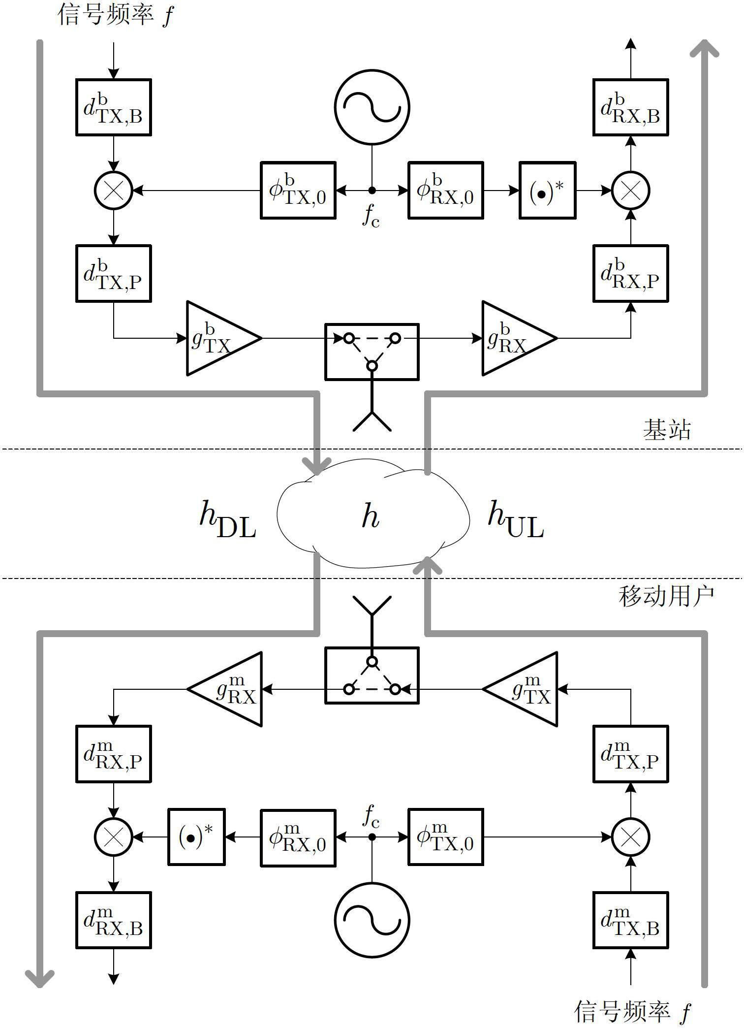
[0023] The present invention uses several terms to describe two parties communicating with each other in various wireless networks. For example, "base station" and "mobile user" in wireless mobile network. The more general terms "reference device" and "non-reference device" are also used in the broader description to re...


PUM


Abstract

The present invention relates to a method for effectively detecting carrier phase difference (CPD) between mutually communicated communication devices on whole signal bandwidth and a corresponding device. The detection of the CPD uses a linear structure of the CPD and the most of the feedback spending is eliminated. The invention describes a compressible digital feedback mechanism and a signaling protocol feedback mechanism. The CPD can be decomposed into a fixed / slow part and a quick variable part, wherein the fixed / slow part is pre-calibrated before communication process and then sent to the correlative communication device, thereby furthermore reducing the feedback spending and improving the detection precision of the CPD. The non-linearity in the sending receiving chain is pre-calibrated, thus the method for detecting the CPD of the linear structure is used for detecting the CPD of the more general structure. The application of the method and device comprises frequency and phase synchronism between a wireless multi-point communication system (also named as a cooperation multi-point communication, namely CoMP in an LTE-advanced system) and a set of base stations.

Description

technical field [0001] The present invention relates to the field of telecommunication systems and wireless communication systems, in particular to the technical field of wireless communication carrier phase detection, and specifically refers to a method for detecting carrier phase difference under mismatch delay between a transmitter and a receiver. Background technique [0002] The data traffic of a wireless mobile network is one of the most important indicators of network performance. The higher the data flow rate, the more mobile users each cell can serve in the network, and the higher the data rate each user can achieve. However, at the edge of the cell, the data rate of mobile users will be extremely low due to the interference of adjacent cells. Statistically, there are more mobile users at the edge of the cell than near the base station, so the average data traffic of the cell will be much lower than the peak data traffic. Generally speaking, the average data traff...

Claims


Application Information

Patent Timeline
Patent Type & Authority Applications(China)
IPC IPC(8): H04L25/02H04W24/00
CPCH04W56/0035H04L25/0232H04W56/00H04L25/0228H04L25/0222H04L25/022
Inventor 王晓安
Owner 王晓安
Learn More