
Communication network, and master device, slave device, multiplexer and switch constituting the communication network

a communication network and master device technology, applied in the field of communication networks, can solve the problems of small percentage, inability to accurately predict the sampling time of packet relay between a master device and a slave device, and may generate mismatches in sampling time, so as to eliminate fluctuations in transfer delay time and improve the sampling time in information transfer

Inactive Publication Date: 2005-03-15
MITSUBISHI ELECTRIC CORP
View PDF25 Cites 49 Cited by
  • Summary
  • Abstract
  • Description
  • Claims
  • Application Information

AI Technical Summary

Benefits of technology

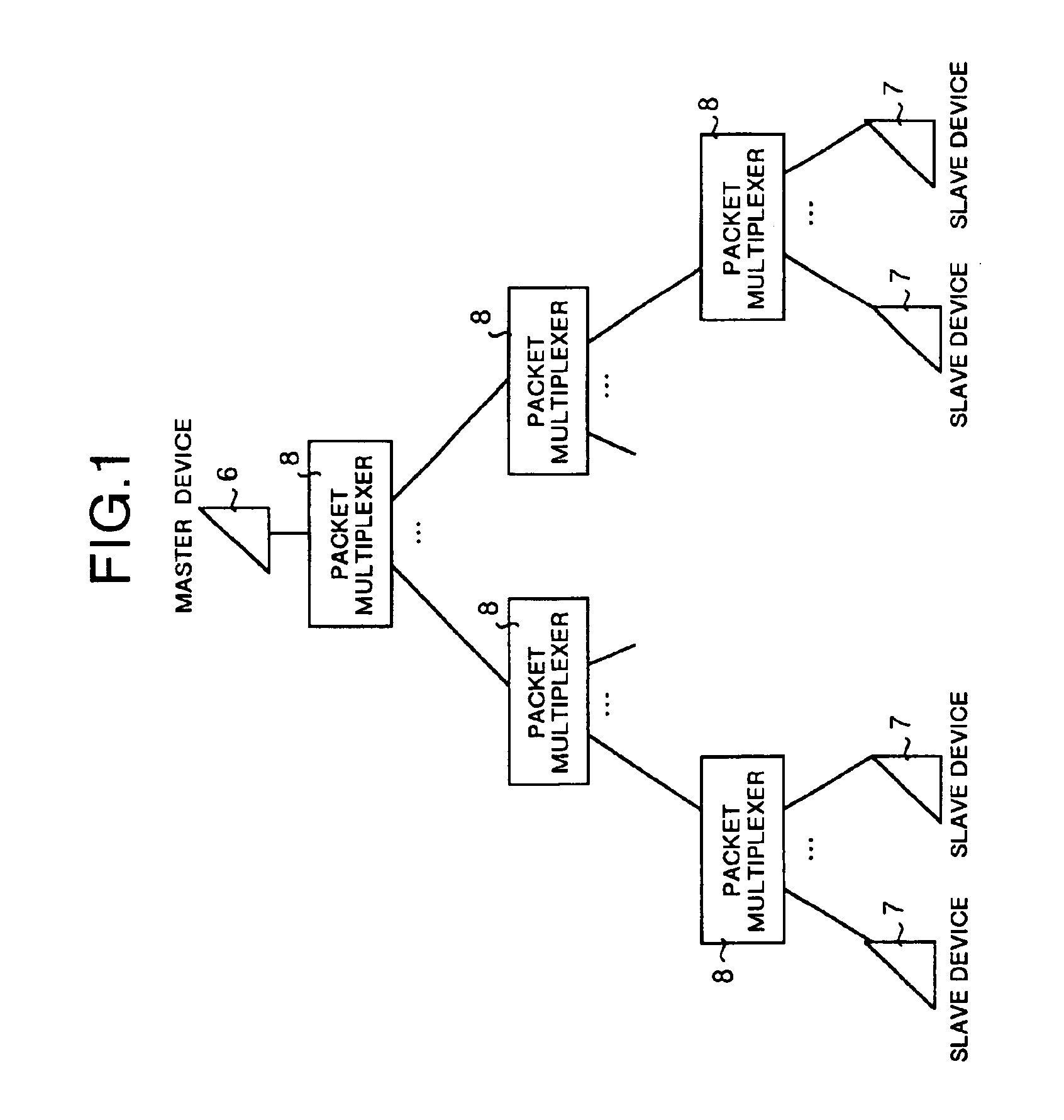
It is an object of the present invention to provide a communication network and a master device for the network, a slave device, a multiplexer and a switch each constituting the communication network which can improve sampling time in information transfer between the master device and each of the slave devices by eliminating fluctuation in a transfer delay time with respect to a specific packet due to a time required for queuing as well as by matching at a high level a transfer delay time in the master device to that in a slave device.
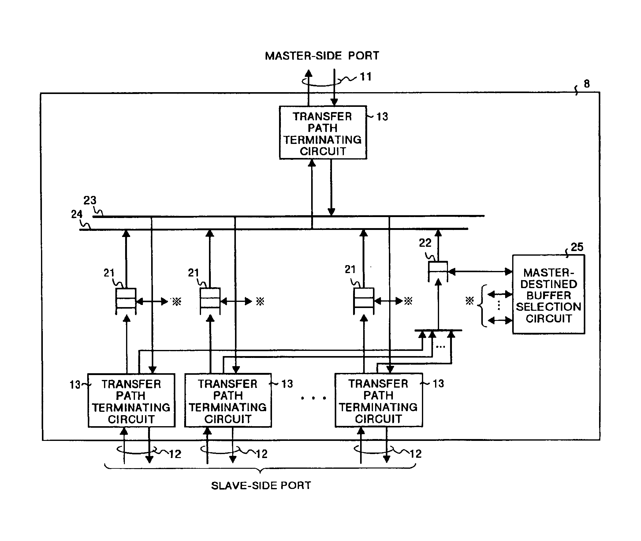
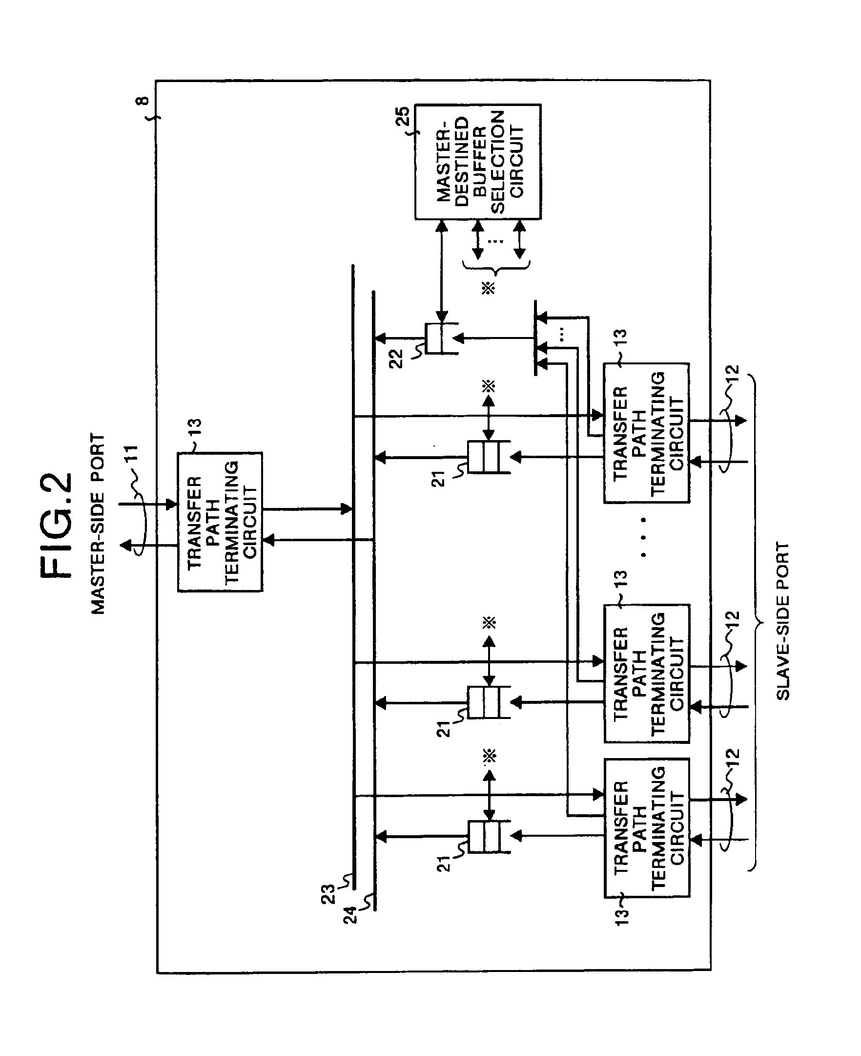
With the present invention, a relay time between the master-side port and slave-side port when relaying specific information with a switch is always equal to a sum of a certain constant period of time and other constant processing delay time (such as a time required for passing through the transfer path terminating circuit or the like), so that fluctuation in a delay time due to a time required for queuing can be eliminated.

Problems solved by technology

A mismatch in the sampling time may be generated during booting of the devices, or when there is a breakdown, or due to a difference in the operation clock frequency in the master device and in the slave device.
In the communication network based on the conventional technology, however, following problems occur when the packet multiplexer as described above is used.
Therefore, there is a problem that precision in sampling time for packet relay between a master device and slave devices equivalent to what has been expressed in the equation (8).
However, the percentage is small as compared to that due to the time required for queuing.

Method used


Image

  • Communication network, and master device, slave device, multiplexer and switch constituting the communication network
  • Communication network, and master device, slave device, multiplexer and switch constituting the communication network
  • Communication network, and master device, slave device, multiplexer and switch constituting the communication network

Examples


embodiment 8

In the communication network according to this embodiment, like in Embodiment 8, a plurality of small-scale communication networks each comprising a master device and a plurality of slave devices are provided, and even when each master device collects sampling information from a slave device in the local small-scale network as well as from a slave device outside the local small-scale network, a delay time in transferring a specific packet in the master device for time setting and that in each slave device are matched to each other with high precision.

FIG. 15 shows an internal configuration of the packet switch 61 according to this embodiment. It should be noted that the same reference numerals are assigned to the same components as those described above and detailed description thereof is omitted herein. In this figure, the reference numeral 62 indicates a packet switch circuit.

Operations of the packet switch 61 according to this embodiment are explained here. Operations of the tran...


PUM


Abstract

In a communication network in which one master device and a plurality of slave devices are connected via a multiplexer to each other in a tree form with the master device provided at the vertex, the master device specifies each of the slave devices via the multiplexer according to a round-robin. Then the slave device transmits specific information for starting used for matching the sampling time to the master device according to the specified order. Finally, the sampling time is adjusted by executing a prespecified operation according to the specific information for returning returned from the master device in response to the specific information for starting.

Description

FIELD OF THE INVENTIONThe present invention relates to a communication network in which one master device and a plurality of slave devices are connected through at least one unit of multiplexer in a tree form with the master device provided at the vertex. This invention more specifically relates to a communication network in which precision in sampling time between the master device and slave device can be improved.BACKGROUND OF THE INVENTIONA conventional type of communication network is described here. FIG. 16 is a view showing a conventional type of communication network disclosed, for instance, in Japanese Patent Publication No. HEI 5-42209. In this figure reference numeral 1 indicates a master device, and reference numeral 2 indicates a slave device. The master device 1 and slave device 2 are connected to each other with an interactive transfer path. Assuming that a sampling cycle is T, information sampled at sampling time T is transmitted to each other according to the samplin...

Claims


Application Information

Patent Timeline
IPC IPC(8): H04J3/08H04L12/44H04J3/06H04J3/24
CPCH04J3/247H04J3/0685
Inventor SODA, KEIICHIICHIHASHI, TATSUKI
Owner MITSUBISHI ELECTRIC CORP
Learn More