Compensation device for thermal lens effect of slab laser

A technology of thermal lens effect and slab laser, which is applied in the field of lasers, can solve the problems of increased laser loss, difficulty in using laser devices, and limited compensation range, etc., and achieves the effects of maintaining stable work, avoiding laser damage, and simple structure

Active Publication Date: 2014-04-02
TSINGHUA UNIV
View PDF7 Cites 0 Cited by
  • Summary
  • Abstract
  • Description
  • Claims
  • Application Information

AI Technical Summary

Problems solved by technology

But there is following problem in above-mentioned compensating device: the compensating method of this compensating device is to make the distance of rod and lens equal to " sum of thermal lens focal length and lens focal length " promptly thermal lens and lens form Keplerian telescope, and this compensating device only when thermal When the focal length of the lens is very small, the "sum of the focal length of the thermal lens and the focal length of the lens" can be used for practical laser devices. The laser device adopts; inserting a cavity mirror into the optical resonator will increase the laser loss, which will lead to a decrease in the laser energy conversion efficiency
This kind of compensation device has the following problems: when the motor drives the spherical mirror to move, it is difficult to ensure that it is always along the optical axis, and the adjustment requirements are very high; the resonant cavity usually contains other components, which will limit the range of compensation

Method used


Image

  • Compensation device for thermal lens effect of slab laser
  • Compensation device for thermal lens effect of slab laser
  • Compensation device for thermal lens effect of slab laser

Examples


Embodiment 1

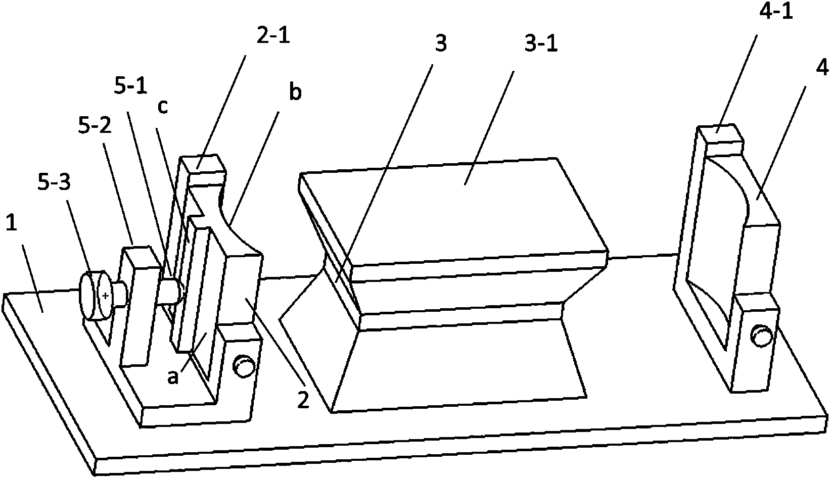
[0043] like figure 1 As shown, one end of the connecting rod 5-1 connected to the connecting rod driving unit 5-3 is provided with an external thread, and the connecting rod driving unit 5-3 is provided with an internal thread matching the external thread, and the rotating connecting rod driving unit 5-3 It can promote the telescopic movement of the connecting rod 5-1 in the horizontal direction. The connecting rod 5-1 of this embodiment runs through the connecting rod support 5-2.

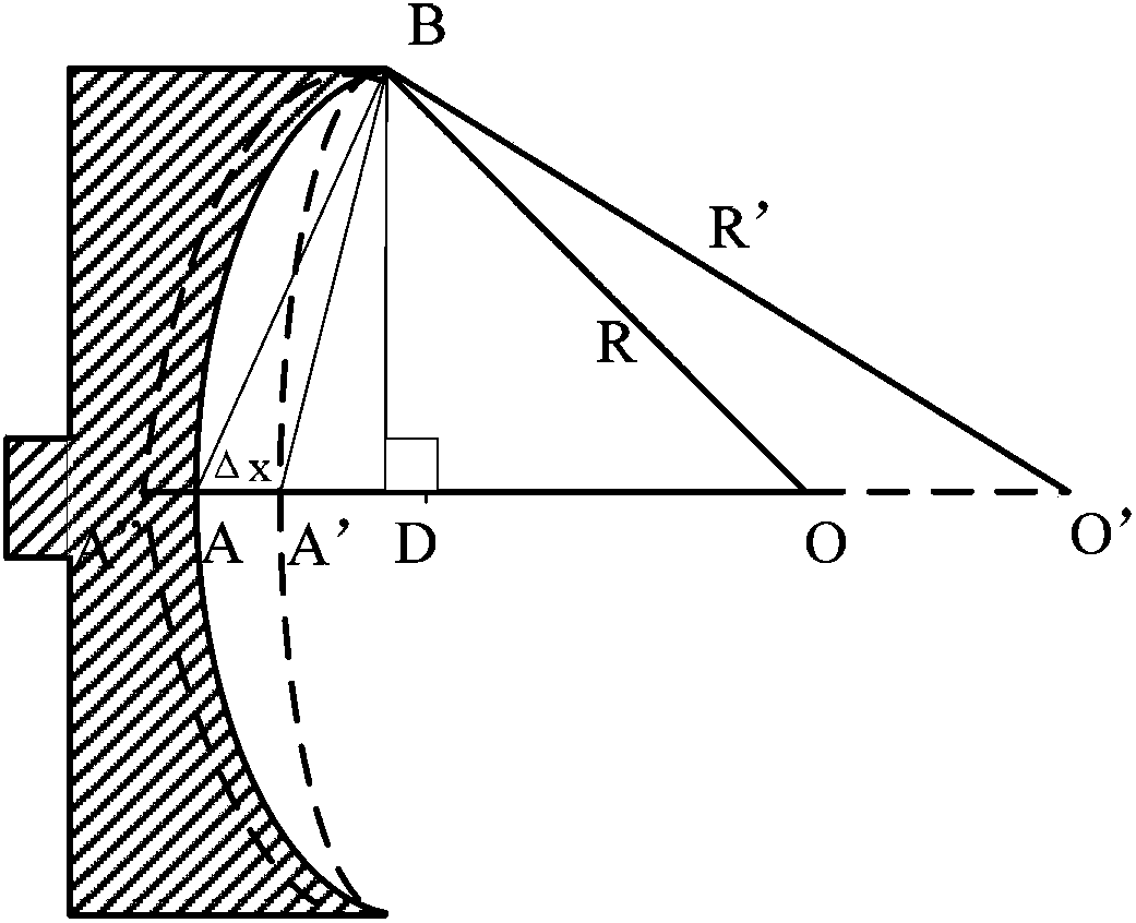
[0044] In this embodiment, the purpose of changing the radius of curvature R of the cavity mirror 2 is to change the force exerted by the connecting rod 5-1 on the outer surface a of the cavity mirror 2 by rotating the connecting rod driving unit 5-3. like figure 1 As shown, the minimum value of the change value Δx of the radius of curvature Δx of the cavity mirror 2 can be realized by manually adjusting the connecting rod drive unit 5-3. The half-width r=10mm, then when Δx=0.1mm, the radius of...

Embodiment 2

[0046] like Figure 4 , the connecting rod 5-1 is a piezoelectric ceramic material, the connecting rod drive unit 5-3 is a piezoelectric ceramic power supply, the connecting rod 5-1 is connected to the connecting rod driving unit 5-3 through a cable, and the connecting rod support 5 in this embodiment The top of -2 has a card slot, and the connecting rod 5-1 is installed in the card slot. Adjusting the voltage of the connecting rod drive unit 5-3 drives the connecting rod 5-1 to expand and contract, so that the force exerted by the connecting rod 5-1 on the outer surface a of the cavity mirror 2 changes, thereby realizing the change of the inner surface b of the cavity mirror 2 The purpose of the radius of curvature R.

[0047] Since the piezoelectric ceramic material can achieve high-precision displacement changes, its displacement accuracy can reach 0.05 μm. Assume that the initial curvature radius of the cavity mirror 2 is R=50mm, and the half-width of the inner surface b ...


PUM


Abstract

The invention discloses a compensation device for a thermal lens effect of a slab laser. The compensation device comprises a base, an endoscope, a laser medium, an output lens, a connecting rod mechanism and a part for uniformly adjusting acting force, wherein the endoscope, the laser medium and the output lens are mounted on the base; the connecting rod mechanism is connected with the endoscope through the part for uniformly adjusting acting force; and the connecting rod mechanism is used for adjusting the radius of curvature of the endoscope and compensating the thermal lens effect of the slab laser along the curve direction of the endoscope by applying an acting force to the outer surface of the endoscope by the part for uniformly adjusting acting force when the pumping power is changed.

Description

technical field [0001] The invention relates to the technical field of lasers, in particular to a compensation device for the thermal lens effect of a slab laser. Background technique [0002] When the laser is working, the pump light energy absorbed by the laser medium, except a part of it is output in the form of laser, most of the other energy is converted into heat and deposited in the laser working material to cause a temperature rise. Under the action of repeated pumping and heat conduction, The temperature gradient in the working substance is continuously increasing, and the existence of the temperature gradient in the working substance makes the working substance with a completely uniform refractive index become a lens-like medium, and the light beam is focused after passing through the working substance, commonly known as thermal self-focusing. Thermal self-focusing not only increases the divergence angle of the laser beam rapidly, which is not conducive to the subs...

Claims


Application Information

Patent Timeline
Patent Type & Authority Patents(China)
IPC IPC(8): H01S3/02H01S3/08H01S3/136
Inventor 巩马理胡震岳黄磊柳强闫平张海涛
Owner TSINGHUA UNIV
Why Eureka
Try Eureka